Redundancy in Layers 1 & 2 OSI Model | Network Redundancy Issues
Redundancy in layers 1 and 2 of the OSI model and the problems of implementing a redundant network are described. Network redundancy is key to maintaining network reliability . Several physical links between devices provide redundant routes. In this way, the network can continue to operate if a single link or port failed. Redundant links can also share traffic load and increase capacity.Several routes must be administered so that no loops occur in layer 2. The best routes are chosen, and an alternative route is available immediately in the event that a main route fails. Expansion tree protocols are used to manage layer 2 redundancy.
Redundancy in layers 1 and 2 of the OSI model
The three-tier hierarchical network design , which uses the core, distribution and access layers with redundancy, attempts to eliminate a single point of failure in the network. Several cable-connected routes between switches provide physical redundancy in a switched network. This improves the reliability and availability of the network. Having alternative physical paths for the data to cross the network allows users to access network resources, despite interruptions to the route.- PC1 communicates with PC4 through a redundant network topology.
- When the network link between S1 and S2 is interrupted, the route between PC1 and PC4 is automatically adjusted to compensate for the interruption.
- When the network connection between S1 and S2 is restored, the route is re-adjusted to route traffic directly from S2 to S1 to reach PC4.
Route redundancy is a solution to provide the necessary availability of several network services by eliminating the possibility of a single point of failure.
Redundancy in layer 1 of the OSI model is represented by the use of several links and devices, but more than just physical planning is needed to complete the network configuration. For redundancy to work systematically, layer 2 protocols of the OSI model, such as STP , must also be used .
Problems with Redundancy
Redundancy is an important part of hierarchical design to avoid interrupting the delivery of network services to users. Redundant networks require the addition of physical routes, but logical redundancy must also be part of the design. However, redundant routes in a switched Ethernet network can cause physical and logical loops in layer 2.- Physical loops in layer 2 can occur as a result of the normal operation of the switches, especially the discovery and forwarding process. When there are several routes between two devices in a network and no expansion tree protocols are implemented on the switches, a loop occurs in layer 2 . A loop in layer 2 can cause three main problems:
- Instability of the MAC database : the instability of the contents of the MAC address table is produced by receiving copies of the same frame on different ports of the switch. Data forwarding can be affected when the switch consumes resources that deal with instability in the MAC address table.
- Broadcast storms : switches can saturate the network with broadcasts incessantly if a process to avoid loops is not implemented. This situation is commonly known as "diffusion storm."
Multiple frame transmission : Multiple copies of the unicast frames may be delivered to the destination stations. Many protocols expect to receive a single copy of each transmission. Multiple copies of the same frame may cause errors that cannot be recovered.
Problem: Instability of the MAC database
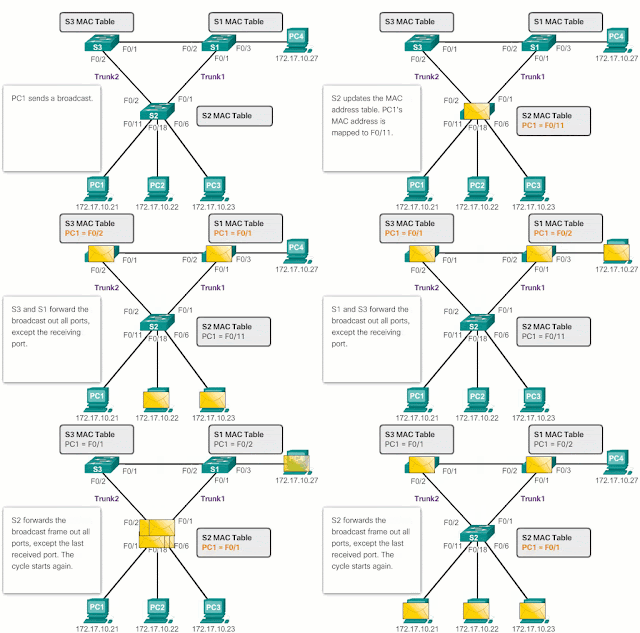
Ethernet frames do not have a life time attribute (TTL) like IP packets. As a result, if there is no mechanism enabled to block the continuous propagation of these frames in a switched network, they continue to propagate between the switches incessantly, or until a link is interrupted and the loop is broken. This continuous propagation between switches can cause instability of the MAC database . This may occur due to the forwarding of broadcast frames.Broadcast frames are forwarded through all switch ports, except for the original input port. This ensures that all devices in a broadcast domain receive the frame. If there is more than one route to resend the frame, an infinite loop can be formed. When a loop occurs, the MAC address table on a switch can constantly change with updates of broadcast frames, which causes the instability of the MAC database.
According to Image 2 :
- PC1 sends a broadcast frame to S2. S2 receives the broadcast frame in F0 / 11. When S2 receives the broadcast frame, it updates its MAC address table to record that PC1 is available on port F0 / 11.
- Because it is a broadcast frame, the S2 forwards the frame through all ports, including the Local_Link1 and the Local_Link2. When the broadcast frame reaches S3 and S1, they update their MAC address tables to indicate that PC1 is available on port F0 / 1 of S1 and on port F0 / 2 of S3.
- Since it is a broadcast frame, S3 and S1 forward the frame through all ports, except the input port. S3 sends broadcast frames from PC1 to S1. S1 sends broadcast frames from PC1 to S3. Each switch updates its MAC address table with the wrong port for PC1.
- Each switch resends the broadcast frame over all its ports, except the input port, which causes the two switches to forward the frame to S2.
- When S2 receives the broadcast frames of S3 and S1, the MAC address table is updated again, this time with the last input received from the other two switches.
This process is repeated again and again until the loop is broken by physically disconnecting the connections that cause it or by turning off one of the switches in the loop.
Problem: Broadcast Storms
A broadcast storm occurs when there are so many broadcast frames trapped in a Layer 2 loop, that all available bandwidth is consumed . As a consequence, there is no bandwidth available for legitimate traffic and the network is no longer available for data communication. This is an effective denial of service.Broadcast storm is inevitable in a network with loops. As more devices send broadcasts over the network, more traffic is concentrated in the loop, which consumes resources. Finally, a diffusion storm is created that causes the network to fail.
There are other consequences of broadcast storms, for example, it may cause the terminal to not work well because of the high processing requirements to maintain such a high traffic load in the NIC.
Detail of the problem with diffusion storms
According to Image 3 :- PC1 sends a broadcast frame to the network with loops.
- The broadcast frame creates a loop between all interconnected switches in the network.
- PC4 also sends a broadcast frame to the network with loops.
- The broadcast frame of PC4 is also trapped in the loop between all interconnected switches, as is the broadcast frame of PC1.
- As more devices send broadcasts over the network, more traffic is concentrated in the loop, which consumes resources. Finally, a diffusion storm is created that causes the network to fail.
- When the network is completely saturated with broadcast traffic that generates a loop between the switches, the switch discards new traffic because it cannot process it.
Since devices connected to a network regularly send broadcast frames, such as ARP requests, a broadcast storm may form in seconds . As a result, when a loop is created, the switched network is quickly deactivated.
Problem: Duplicate Unicast Frames
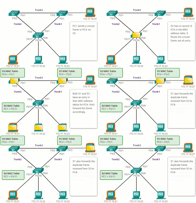
Broadcast frames are not the only type of frames that are affected by loops. Unicast frames sent to a network with loops can generate duplicate frames that reach the destination device.Most upper layer protocols are not designed to recognize duplicate transmissions or deal with them. In general, protocols that use a sequence numbering mechanism assume that the transmission has failed and that the sequence number has been recycled for another communication session. Other protocols attempt to send the duplicate transmission to the appropriate upper layer protocol to be processed and possibly discarded.
Layer 2 LAN protocols, such as Ethernet, lack mechanisms to recognize and eliminate frames that form incessant loops . Some layer 3 protocols implement a TTL mechanism that limits the number of times a layer 3 network device can transmit a packet again. Layer 2 devices, which lack this mechanism, continue to relay the traffic that generates loops indefinitely. STP , a mechanism that serves to prevent loops in layer 2, was developed to address these problems.
To prevent these problems from occurring in a redundant network, some kind of expansion tree must be enabled on the switches . By default, the expansion tree is enabled on Cisco switches to prevent loops in Layer 2.
Detail of the problem with diffusion storms
According to Image 4 :- PC1 sends an unicast frame to PC4.
- The S2 does not have any input for PC4 in its MAC table, so it saturates all the ports of the switch with the unicast frame to try to find PC4.
- The frame reaches switches S1 and S3.
- S1 does not have a MAC address entry for PC4, so it resends the frame to PC4.
- S3 also has an entry in its MAC address table for PC4, so that it forwards the unicast frame through Trunk Link3 to S1.
- S1 receives the duplicate frame and forwards it to PC4.
- PC4 has now received the same frame twice.


No comments:
Post a Comment