Wednesday 21 August 2019

Network Layer Protocols

Network Layer Protocols

Let's see how many network layer protocols exist and which ones are usually implemented. Also the IPv4 and IPv6 packages.

NETWORK LAYER

The network layer or layer 3 of the OSI model provides services to allow the terminals to exchange data on the network. The Network layer uses 4 basic processes (End-to-end transport processes):


  • Terminal Addressing : The terminals must be configured with a unique IP address to identify them in the network.
  • Encapsulation : The network layer encapsulates the protocol data unit (PDU) of the transport layer to a packet (add IP header information)
  • Routing or Routing : The network layer provides services to direct packets to a destination host on another network
  • Decapsulation : Once the network layer uncapsulates the packet, the layer 4 PDU that is obtained is transferred to the appropriate service in the transport layer.

Each router that crosses a packet before reaching the destination host is called a "jump."

NETWORK LAYER PROTOCOLS

There are several network layer protocols. However, there are only two network layer protocols that are usually implemented:


  • Internet Protocol version 4 (IPv4)
  • Internet Protocol version 6 (IPv6)

Old Network Layer Protocols


  • Novell internetwork packet exchange (IPX)
  • AppleTalk
  • Offline network service (CLNS / DECNet)

IP FEATURES

IP was designed as a protocol with low overhead.  This means that it only provides the necessary functions to send a packet from a source to a destination through an interconnected network system. The protocol was not designed to track or manage packet flow.

The following describes the basic characteristics of IP:

IP: NO CONNECTION

IP has no connection, which means that an exclusive full connection is not generated before sending the data and then the following happens:


  • The sender does not know if the receiver is listening or if the message arrived on time.
  • The receiver does not know that data is coming.

 IP: MINIMUM SERVICE DELIVERY

To be unreliable means that IP does not have the functionality to manage or recover packets not received or damaged . This is because, although IP packets are sent with information about the delivery location, they do not have information that can be processed to inform the sender if the delivery was successful.

IP: INDEPENDENT OF THE MEDIA

Regardless of the means it means that the transport of IP packets is not limited to a particular medium (it can be transmitted by copper cables, optical signals or wireless radio signals). However, the network layer takes into account one of the most important characteristics of the medium, the " maximum transmission unit " (MTU) which is the maximum size of PDUs that each medium can carry.

The data link layer passes the MTU value to the network layer. The network layer then determines what size the packets can be. A router must divide the packet when it is forwarded from one medium to another with a lower MTU. This process is called " packet fragmentation " or "fragmentation."

Address Resolution Protocol ARP In Networking

Address Resolution Protocol ARP In Networking

This article is an introduction to the Address Resolution Protocol ARP In Networking. You will learn what it ARP, how ARP works, what is purpose of ARP.

Remember that each device in an Ethernet network has an IP address and an Ethernet MAC address. When a device sends an Ethernet frame, it contains these two addresses:


  • Destination MAC Address : The MAC address of the Ethernet NIC, which is the address of the final destination or router.
  • Source MAC address: the MAC address of the sender's Ethernet NIC.


DIFFERENCES BETWEEN MAC AND IP

The combination of MAC and IP facilitates end-to-end communication. While the Layer 2 (MAC) addresses are used to move the frame within the local network. Layer 3 (IP) addresses are used to move packets across remote networks.

Main differences:


  • The MAC address does not change ("it is a person's ID"), while the IP address is similar to a person's address.
  • The MAC address is known as " physical address"  because it is physically assigned to the host NIC. The IP address is known as the " logical address"  because it is logically assigned.
  • In order for a PC to communicate, both the physical MAC address and the logical IP address are required

FUNCTIONS OF THE Address Resolution Protocol ARP in networking

The sending node needs a way to find the MAC address of the destination for a given Ethernet link and this is how ARP appears, which allows the origin to request the MAC address of the destination. The request is based on the Layer 3 address of the destination (known by the origin).


  • To determine the destination MAC address, the device uses ARP. ARP provides two basic functions:
  • Resolution of IPv4 addresses to MAC addresses
  • Maintenance of an assignment table
The functions of the ARP are as follows:
  • Resolution of IPv4 addresses to MAC addresses : The ARP table or ARP cache (which is stored in the device RAM), allows you to find the MAC address that is assigned to an IPv4 address.
  • Maintenance of an assignment table:
  • ARP uses the ARP Request and the ARP Response to perform its functions.

For each device, an ARP cache timer removes ARP entries that have not been used for a specified period.

PROBLEMS IN ARP

There are two types of problems regarding ARP:


  • ARP broadcasts : ARP requests can saturate the local segment.
  • ARP impersonation : (ARP poisoning) This is a technique used by an attacker to respond to an ARP request from an IPv4 address that belongs to another device, such as the default gateway. The attacker sends an ARP response with its own MAC address. The ARP response recipient adds the wrong MAC address to the ARP table and sends these packets to the attacker.


Tuesday 20 August 2019

How Switch & MAC Address works in LAN

How Switch & MAC Address works in LAN

This article will give you a brief about component of switch networks and How Switch & MAC Address works in LAN. First we will learn about the basic devices of networks and then we will study the working of Cisco LAN switch and MAC address in detail. This article is very helpful for CCNA students.
The essential hardware for network connectivity is included in the list below. First we will review some devices that are no longer in use and the most important ones, such as switches and routers, we will talk later.


  • Repeaters: those that extend the distance so that network traffic can be transferred on 
  • a particular type of transmission medium.
  • Hubs: which are used to connect nodes to each other when using a star topology, such as 100Base-T
  • Switches: those that form fast point-to-point connections for all devices connected to them.
  • Bridges: which are intelligent repeaters that send traffic from one segment to another only when the traffic is destined for that other segment.
  • Routers: which can intelligently route network traffic in many ways.
  • Gateways: these are specific application interfaces that link the seven layers of the OSI model when they are different at one or all levels
  • Short-range modems for small connections between buildings

WHAT IS A SWITCH?

An Ethernet switch is a layer 2 device that creates a MAC address table to make a
forwarding decision for each frame. Sometimes, the MAC address table is called "addressable content memory table" (CAM)

Switches, as the name implies, can switch connections from one port to another and very quickly. They are connection oriented and dynamically switch between their different ports to create these connections. The interesting thing is that, because connections from one port to another on the switch are carried out as needed (and not sent to ports that are not involved in traffic), the switches can help
eliminate collisions from traffic caused by segments that do not communicate. Unlike the Ethernet hubs that repeat the bits through all ports except the input, an Ethernet switch consults a MAC address table to make a forwarding decision for each frame.

HOW SWITCH FINDS MAC ADDRESSES?

The switches dynamically elaborate the CAM by monitoring the source MAC addresses. The switch forwards frames if it finds a match between the destination MAC address of the frame and an entry in the MAC address table. There are two processes that are performed for each Ethernet frame that enters a switch:

EXAMINE THE SOURCE MAC ADDRESS

Each frame that enters a switch is checked for new addresses. This is done by examining the source MAC address of the frame and the port number through which it entered the switch.

  • If the source MAC address does not exist, it is added to the table, along with the input port number.
  • If the source MAC address exists, the switch updates the update timer for that entry. By default, most Ethernet switches save an entry in the table for five minutes .

EXAMINE THE DESTINATION MAC ADDRESS

If the destination MAC address is a unicast address, the switch searches for a match between the destination MAC address of the frame and an entry in the MAC address table.

  • If the destination MAC address is in the table, it resends the frame through the specified port.
  • If the destination MAC address is not in the table, the switch forwards the frame through all ports, except the input. This is known as "unknown unicast."
If the destination MAC address is broadcast or multicast, the frame is also sent over all ports, except the incoming one.

SWITCH MAC ADDRESS TABLE


For a better understanding let's see the following image and the following steps:


  • The switch receives a broadcast frame from PC 0 on port 0.
  • The switch enters the source MAC address and the switch port that received the frame in the address table.
  • Since the destination address is broadcast, the switch saturates all ports by sending the frame, except the port that received it.
  • The destination device responds to the broadcast with a unicast frame addressed to PC 0
  • The switch enters the source MAC address of PC 1 and the number of the switch port that received the frame into the address table.
  • Now the switch can send frames between the source and destination devices without saturating the traffic, since it has entries in the address table that identify the associated ports.
  • When a switch sends traffic to a destination MAC address that is not in its MAC table, it will be forwarded to all ports except the source port.

FRAME FORWARDING METHODS OF CISCO SWITCHES

The switches use one of the following forwarding methods for switching data between ports on the network:

  • Storage Switching and forwarding:  Receive the full frame and calculate the Cyclic Redundancy Check (CRC). If the CRC is valid, the switch searches for the destination address and sends the frame through the correct port.
  • The CRC uses a mathematical formula based on the number of bits (numbers one) to determine if it has an error.
  • Cutting Method Switching : The switch does not perform any verification of errors in the frame and has two variants:
  • Fast forwarding  (typical): The lowest latency level resends the packet immediately after reading the destination address.
  • Fragment-free : The switch stores the first 64 bytes of the frame before forwarding. Most network errors and collisions occur in those first 64 bytes.
  • Buffering memory on switches : Use this technique to store frames before sending them or when the destination port is busy due to congestion.
There are two methods of memory buffering: port-based memory and shared memory.

  • Port-based memory buffer : frames are stored in queues connected to specific input and output ports
  • Shared memory buffer : deposits all frames in a common memory buffer shared by all switch ports.
For asymmetric switching (ports with different speeds), shared memory buffering is optimal because the number of frames stored in the buffer is limited only by the size of the memory buffer as a whole.

CONFIGURING THE PORTS OF A SWITCH

Two of the most basic parameters of a switch are bandwidth and duplex parameters for each individual switch port. It is essential both coincide between the switch port and the connected devices, such as a computer or other switch.

There are two types of duplex parameters used for communications in an Ethernet network:

  • Full duplex : both ends of the connection can send and receive data simultaneously.
  • Medium duplex : only one end of the connection can send data at a time.

AUTO-MDX

This feature helps reduce configuration errors since the switch detects the type of cable connected to the port and configures the interfaces appropriately

Ethernet Protocols and Features

Ethernet Protocols and Features 

In this article you will learn about the Ethernet Protocols and Features. Ethernet is the predominant LAN technology in the world and works in the data link layer and in the physical layer. The Ethernet protocol standards define the format, size, timing and coding of frames in a network communication; It is therefore important to know the Ethernet standards that define Layer 2 protocols and Layer 1 technologies.

Ethernet has evolved since its creation in 1973. The first versions of Ethernet were relatively slow, with a speed of 10 Mbps, while the most recent ones run at 10 Gbps and even faster.

Some Key features of Ethernet are:


  • Most used LAN technology.
  • It works in the data link layer and in the physical layer.
  • Family of network technologies defined in the IEEE 802.2 and 802.3 standards.
  • Supports data bandwidths of 10, 100, 1000, 10,000, 40,000 and 100,000 Mbps (100 Gbps).

ETHERNET ENCAPSULATION

As I mentioned, Ethernet works in layer 1 and layer 2, and precisely, it operates in two separate sub-layers of the data link layer :

  1. Logic Link Control (LLC) 
  2. MAC 

SUBLAYER LLC

The LLC Sublayer (Logical Link Control or Logical Link Control) is implemented by software (its implementation is hardware independent) and is used to communicate with the upper layers of the protocol suite. The LLC takes the protocol data from the network, which is usually an IPv4 packet, and adds control information to help distribute the packet to the destination node. On a computer, the LLC can be considered the NIC driver software. The NIC controller is a program that interacts directly with the NIC hardware to transfer data between the MAC sublayer and physical media.


 MAC SUBLAYER

The MAC sublayer (Media Access Control or Media Access Control) constitutes the lower sublayer of the data link layer and is implemented by hardware, usually in the NIC of the PC.
It has two main responsibilities:


  • Data encapsulation : Includes frame arming before transmission and frame disarming at the time of reception and provides three main functions:
  • Frame delimitation : used to identify a group of bits that make up a frame. These delimiter bits provide synchronization between the transmission and reception nodes.
  • Addressing : The encapsulation process contains the Layer 3 PDU and also provides data link layer addressing.
  • Error detection : each frame contains a trailer used to detect transmission errors.


To assemble the frame, the MAC layer adds a header and a trailer to the PDU of the network layer.


  • Media access control : It is responsible for placing the frames in the media and removing them from them (hence the name). This sublayer communicates directly with the physical layer.

The underlying logical topology of Ethernet is a multi-access bus in which all devices (nodes) of a single network segment share the medium. Ethernet is a contention network method, where any device can attempt to transmit data through the shared medium as long as it has data to send. To detect and resolve collisions, the process of multiple access by carrier detection with collision detection (CSMA / CD) in the mid-duplex Ethernet LANs is used.

ETHERNET FRAME FIELDS

The Ethernet II and IEEE 802.3 standards define that the minimum Ethernet frame size is 64 bytes, and the maximum is 1518 bytes and the following are taken into account:


  • A length less than 64 bytes is considered a “collision fragment” or “runt frame”.
  • All frames that are smaller than the minimum or greater than the maximum are discarded.
  • It is possible that discarded frames originate in collisions or other unwanted signals and, therefore, are considered invalid.

Ethernet frame Fields table
FIELDSDESCRIPTION
Preamble and Frame Start DelimiterThe Preamble (7 bytes) and Frame Start Delimiter (SFD) fields, also called “frame start” (1 byte), are used for synchronization between sending and receiving devices.
Destination MAC addressThis 6-byte field is the identifier of the desired recipient.
Source MAC addressThis 6-byte field identifies the NIC or the source interface of the frame.
EtherTypeThis 2-byte field identifies the upper layer protocol encapsulated in the Ethernet frame.
DataThis field (46 to 1500 bytes) contains the encapsulated data of an upper layer, which is a Layer 3 PDU (an IPv4 packet). All frames must be at least 64 bytes long.
FCS (Frame Verification Sequence Field)(4 bytes) is used to detect errors in the frame. Use a cyclic redundancy check (CRC), if the calculations match the source and the receiver, no error occurred.

ETHERNET MAC ADDRESSES

An Ethernet MAC address is a 48-bit binary value expressed as 12 hexadecimal digits (4 bits per hexadecimal digit).

The decimal system is a base 10 number system, the hexadecimal system is a base 16 system, use the numbers from 0 to 9 and the letters from A to F

It's important to know:

  • The hexadecimal system is represented in writing by means of the value preceded by "0x". Example: "0x0A" and "0x73"
  • The hexadecimal value is used to represent Ethernet MAC addresses and IP addresses version 6 (IPv6).

MAC ADDRESS STRUCTURE

The MAC address value is the result of the standards implemented by the IEEE in order to guarantee unique addresses for each Ethernet device. The IEEE assigns the provider a 3-byte (24-bit) code, called “unique organization identifier (OUI)”.

The IEEE requires a provider to follow two simple rules:

  • They must use the OUI assigned to the provider as the first 3 bytes.
  • All MAC addresses with the same OUI must be assigned a unique value in the last 3 bytes.

FRAME PROCESSING

Often, the MAC address is known as " physical address (BIA) " because, historically, this address is physically recorded in the read-only memory (ROM) of the NIC. In other words, it is permanently encoded in the ROM chip.

This is how it works: When the computer starts up, the first thing the NIC does is copy the MAC address of the ROM to RAM. When a device forwards a message to an Ethernet network, it attaches the header information to the frame (which contains the source and destination MAC addresses).

MAC ADDRESS REPRESENTATIONS

MAC addresses have the following characteristics:

  • They can be represented with two points, dashes or periods, and are not case sensitive.
  • 00-60-2F-3A-07-BC, 00: 60: 2F: 3A: 07: BC, 0060.2F3A.07BC and 00-60-2f-3a-07-bc are valid representations of the same MAC address.
On a Windows host, the ipconfig / all command can be used to identify the MAC address of an Ethernet adapter

 UNICAST MAC ADDRESS

Unique address used when a frame is sent from a single transmitting device to a single receiving device. The source MAC address must always be unicast.

MAC BROADCAST ADDRESS

It is used when a frame is sent from a single transmitting device to all devices in the network.
Broadcast packets have a destination IPv4 address that contains only numbers one (1) in the host portion , meaning that all hosts on that local network (broadcast domain) will receive and process the packet. Many network protocols, such as DHCP and ARP, use broadcast.
Another feature is that when the IPv4 broadcast packet is encapsulated in the Ethernet frame, the destination MAC address is the FF-FF-FF-FF-FF-FF broadcast MAC address in hexadecimal (48 numbers one in binary).

MULTICAST MAC ADDRESS

Multicast addresses allow a source device to send a packet to a group of devices. There are some things to keep in mind:
  • The multicast MAC address is a special value that begins with 01-00-5E in hexadecimal (the remaining portion is created by converting the lower 23 bits of the IP address of the multicast group into six hexadecimal characters).
  • The range of IPv4 multicast addresses ranges from 224.0.0.0 to 239.255.255.255 .
  • The IPv6 multicast address range begins with FF00 :: / 8 .

Data Link Layer Protocols Characteristic and Purpose

Data Link Layer Protocols Characteristic and Purpose


In this post we explain the Data Link Layer Protocols of the OSI model (Layer 2) as well as its characteristics, purposes. 

WHAT IS THE DATA LINK LAYER


The OSI data link layer is responsible for the exchange of Ethernet frames between the source and destination nodes through a physical network medium. The data link layer receives packets from a higher layer protocol and directs them to a protocol of the same characteristics (IPv4 or IPv6). This upper layer protocol does not need to know what media the communication uses.

DATA LINK SUB-LAYERS

The data link layer is divided into two sub-layers:


  • Logical Link Control: communicates with the network layer, places information in the frame that identifies which network layer protocol is used for the frame. This information allows several Layer 3 protocols, such as IPv4 and IPv6, to use the same network interface and the same means.
  • Media Access Control: defines the processes of access to the medium that the hardware performs. It provides data link layer addressing and access to various network technologies.

MEDIA ACCESS CONTROL

The technique used to place and remove the plot of the media is called the method of access control to the media.

PROVISION OF MEDIA ACCESS

During the same communication, different methods of access control to the medium may be necessary. Each network environment that packets encounter when they travel from a local host to a remote host can have different characteristics.

DATA LINK LAYER STANDARDS

Finally, we will see some standards that govern Layer 2. Unlike the protocols of the upper layers of the TCP / IP suite, data link layer protocols are generally not defined by the request for comments (RFC).

DATA LINK LAYER STANDARDS

Standardization body
Network standards
IEEE
802.2: Logical link control (LLC)
802.3: Ethernet
802.4: Token bus
802.5: token pass
802.11: wireless LAN (WLAN) and mesh (Wi-Fi certification)
802.15: Bluetooth
802.16: WiMax
ISO
High level data link control (HDLC)
ISO 9314: FDDI media access control (MAC)
ITU-T
G.992: ADSL
G.8100 - G.8199: MPLS aspects of transport
Q.921: ISDN
Q.922: Frame Relay
ANSI
X3T9.5 and X3T12: Fiber Distributed Data Interface (FDDI)

Monday 19 August 2019

Types of Network Media Classification | UTP | fiber optic

Types of Network Media Classification:

In this post we briefly discuss the types of network media of the Physical Layer which are

  • Copper wiring / UTP
  • Fiber optic 
  • Wireless media.

There are three basic formats of network media: copper cable, fiber optic cable and wireless connection. Now we go on to detail each one of them.

COPPER CABLE

The networks use copper media because they are economical and easy to install , and have low resistance to electric current. However, copper media is limited by distance and signal interference such as:


  • Electromagnetic interference (EMI) or radio frequency interference (RFI): Possible sources of EMI and RFI include radio waves and electromagnetic devices such as fluorescent lights or electric motors.
  • Crosstalk : this is a disturbance caused by the electric or magnetic fields of a signal from a wire to the signal from an adjacent wire.

To counteract the negative effects of EMI and RFI, some types of copper wires are packaged with a metal shield and require proper grounding.

Within copper media there are three main types of copper media that are used in networks:


  1. Unshielded twisted pair (UTP)
  2. Shielded Twisted Pair (STP)
  3. Coaxial

UNSHIELDED TWISTED PAIR (UTP) CABLE

UTP cabling is used to interconnect network hosts with intermediary network devices, such as switches and routers.
In LAN networks, the UTP cable consists of four pairs of color-coded wires that are twisted together and coated with a flexible plastic sheath that protects them from minor physical damage. The braiding of the wires helps to protect against interference from signals from other wires.

Types of UTP cables:


Depending on the different situations, UTP cables may need to be armed according to different wiring conventions.


  • Direct Ethernet cable : Usually used to interconnect a host with a switch and a switch with a router.
  • Ethernet crossover cable: cable used to interconnect similar devices. For example, switch to a switch, a host to a host or a router to a router.
  • Console cable: Cisco-exclusive cable used to connect a workstation to a console port of a router or switch.

SHIELDED TWISTED PAIR (STP) CABLE

Shielded twisted pair (STP) provides better noise protection than UTP wiring. However, compared to the UTP cable, the STP cable is much more expensive and difficult to install . Like the UTP cable, the STP uses an RJ-45 connector.
The STP cable combines shielding techniques to counteract EMI and RFI , and wire braiding to counteract crosstalk . For maximum shielding benefits, STP cables are terminated with special shielded STP data connectors. If the cable is not properly grounded, the shield can act as an antenna and pick up unwanted signals.

COAXIAL CABLE

The coaxial, coaxcable or coax cable gets its name from the fact that there are two conductors that share the same axis (two concentric conductors). While the UTP cable essentially replaced the coaxial cable in modern Ethernet installations, the coaxial cable design was adapted for wireless installations and cable Internet installations.

FIBER OPTIC CABLE

Currently, fiber optic cabling is used in four types of industries:

  • Business networks : fiber optic is used for trunk cabling applications and for interconnecting infrastructure devices.
  • Fiber-to-the-Home (FTTH) : Fiber to the home is used to provide always active broadband services to homes and small businesses.
  • Long-range networks : service providers use them to connect countries and cities.
  • Underwater cable networks : they are used to provide reliable high speed and high capacity solutions that can survive in adverse underwater environments over transoceanic distances.
Among the properties of fiber optic cabling, the following stand out:

  • It transmits data over longer distances and bandwidths greater than any other network media
  • It transmits signals with less attenuation and is totally immune EMI and RFI.
  • Flexible but thin fiberglass threads extremely thin and transparent very pure glass, not much thicker than human hair.
  • The bits are encoded in the fiber as pulses of light. The fiber optic cable acts as a waveguide, or a "light pipe", to transmit light between the two ends with minimal signal loss.

TYPES OF FIBER OPTIC CABLES

The types of fiber optic media are as follows:

  • Single mode fiber optic (SMF) : it consists of a very small core and uses expensive laser technology to send a single beam of light, as shown in figure 1. It is widely used in long-distance situations that cover hundreds of kilometers, as applications Cable TV and long distance telephony.
  • Multimode fiber optic (MMF) : consists of a larger core and uses LED emitters to send pulses of light. In particular, the light of an LED enters the multimode fiber at different angles.
One of the prominent differences between multimode and singlemode fiber optics is the amount of scattering, which refers to the extent of light pulses over time. The more dispersion there is, the greater the loss of signal power

 WIRELESS MEDIA

These data communications are made using radio and microwave frequencies. Wireless technology is important in the following areas:

  • Coverage area: There are certain construction materials used in buildings and structures, in addition to local land, which limit effective coverage.
  • Interference : may be affected by common devices such as home cordless phones, some types of fluorescent lights, microwave ovens and other wireless communications.
  • Security : devices and users without authorization to access the network can gain access to the transmission.
  • Shared media: WLAN operates in half-duplex, which means that only one device can send or receive at a time. The wireless medium is shared among all wireless users. The more users that need access to the WLAN simultaneously, each will get less bandwidth

TYPES OF WIRELESS MEDIA

  • Wi-Fi (IEEE 802.11 Standard): Wireless network technologies (WLAN) use a contention protocol called multiple carrier carrier collision prevention access (CSMA / CA)
  • Bluetooth (IEEE 802.15 Standard): Wireless Personal Area Network Standard (WPAN) uses a device pairing process between a distance of 1-100 meters.
  • Wi-Max  (IEEE 802.16 Standard): Known as Global Interoperability for Microwave Access (WiMax). It uses a point-to-multipoint topology to provide wireless broadband access.

WIRELESS LAN

In general, a wireless LAN requires the following network devices:

  • Wireless Access Point (AP): concentrates users' wireless signals and connects to the existing copper-based network infrastructure, such as Ethernet. Home and small business wireless routers integrate the functions of a router, a switch and an access point into a single device.
  • Wireless NIC adapters : provide wireless communication capability to each host in the network.

Physical Layer Protocols Features & Characteristics

Physical Layer Protocols Features & Characteristics

This article of Network Access will describe the Physical Layer Protocols their functions and protocols that manage data transmission.

NETWORK CONNECTIONS

Whether it is a connection to a local printer at home or to a website in another country, in order for any network communication to occur, a connection to a local network must first be established . A physical connection can be a cable connection or a wireless connection using radio waves. The type of physical connection used depends entirely on the network configuration. For example, it may be that a desktop or laptop PC physically connects, via cables, to a shared switch. This type of configuration is called a wired network . Data is transmitted through a physical cable.

Or, it may also be the case of wireless connections for laptops, tablets and smartphones. In the case of wireless devices, data is transmitted by radio waves; where the devices that are in a wireless network must be connected to a wireless access point (AP - Access Point).

NETWORK INTERFACE CARD (NIC)

Network interface cards (NICs) connect a device to the network . Ethernet NICs are used for wired connections, while wireless local area network (WLAN) NICs are used for wireless connections. Devices for end users can include one type of NIC or both.
It is worth mentioning that cable-connected devices do not need to share network access with other devices (each device connected by cable has a separate communication channel through its own Ethernet cable), unlike wireless devices (where several devices they access the network simultaneously and consequently the performance may be slower).

PURPOSE OF THE PHYSICAL LAYER

The physical layer of the OSI model provides the means of transporting the bits that make up a frame of the data link layer through the network means. As well as:


  • Accept a full frame from the data link layer
  • It encodes it as a series of electrical, optical or radio wave signals that represent the bits in each frame that are transmitted to local media.

PHYSICAL LAYER MEDIA

There are three basic formats of network media:
  • Wired Media : the signals are patterns of electrical pulses.
  • Fiber optic cable : the signals are light patterns.
  • Wireless Media: signals are patterns of microwave transmissions.

 PHYSICAL LAYER STANDARDS

The physical layer consists of electronic circuits, media and connectors developed by engineers. That is why the main organizations specialized in electrical engineering and communications define the standards that govern this hardware, for example, some of them are:


  • International Telecommunications Union (ITU)
  • International Organization for Standardization (ISO)

  • Commission (FCC) of the United States and the European Telecommunications Standards Institute (ETSI)
  • American National Standards Institute (ANSI)
  • Association of Telecommunications Industries (TIA) and Association of Electronic Industries (EIA)
  • Institute of Electrical and Electronic Engineers (IEEE)
  • National telecommunications regulatory authorities, including the Federal Communication

FUNCTIONS OF THE PHYSICAL LAYER

The physical layer standards cover three functional areas:

  • Physical components
  • Coding
  • Signaling

 PHYSICAL COMPONENTS

They are the electronic devices of hardware, media and connectors that transmit and transport the signals to represent the bits. All hardware components, such as NICs, interfaces and connectors, materials and cable design, are specified in the standards associated with the physical layer.

CODING

Encoding is a method used to convert a transmission of data bits into a predefined "code." In the case of networks, the coding is a voltage or current pattern used to represent the bits; 0 and 1. In addition to creating codes for the data, the physical layer coding methods can also provide control codes, such as identifying the beginning and end of a frame.Network coding methods include:

  • Manchester coding
  • No return to zero (NRZ)

 SIGNALING

The physical layer must generate the wireless, optical or electrical signals that represent the "1" and the "0" in the media. The bit representation method is called the signaling method .

The signals can be transmitted in two ways:

  • Asynchronous: data signals are transmitted without an associated clock signal. Therefore, the frames require start and stop indicators.
  • Synchronous: data signals are sent together with a clock signal that occurs in uniformly spaced time duration called "bit time."

CHARACTERISTICS OF THE PHYSICAL LAYER

Within the transfer of data in the physical layer we handle two important terms:

  •  Bandwidth : Ability of a medium to transport data is generally measured in kilobits per second (kbps), megabits per second (Mbps) or gigabits per second (Gbps)

Occasionally, bandwidth is thought of as the speed at which the bits travel, however, this is not adequate. For example, in 10 Mbps and 100 Mbps Ethernet, the bits are sent at the speed of electricity. The difference is the number of bits that are transmitted per second.

  • Performance : is the measure of bit transfer through the media for a certain period of time. Many factors influence performance: The amount of traffic, the type of traffic, the latency created by the number of network devices found between origin and destination.
  • Latency : refers to the amount of time, including delays, that it takes data to transfer from one point to another.


Data Encapsulation in Computer Networks | Encapsulation Vs Decapsulation

Data Encapsulation in Computer Networks | Encapsulation Vs Decapsulation

This article is describe Data Encapsulation in Computer Networks. In order to understand the process of data encapsulation , you should aware with terms message segmentation and protocol data units (PDUs).

What is MESSAGE SEGMENTATION?

When a message is sent over the computer network from a source to a destination, it is done through a massive and continuous transmission of bits. This means that no other device can send or receive messages on the same network while this data transfer is in progress, which causes significant delays. In addition, if a link fails in the infrastructure of the interconnected network during transmission, the entire message would be lost and would have to be re-transmitted completely. Then it is better to divide the data into smaller and more manageable parts to send them over the network. This division is called segmentation and has both advantages and disadvantages:


  • Advantages: By sending smaller individual parts from the origin to the destination, various conversations can be interleaved in the network, called multiplexing . Segmentation can increase the efficiency of network communications, that is, if part of the message fails to reach the destination due to a network failure or congestion, only missing parts must be re-transmitted.
  • Disadvantage: Level of complexity that is added to the process.

What is PDU (PROTOCOL DATA UNITS)?

The Protocol Data Units (PDUs) describe a portion of data in any layer of a network model:

  • Data: General term used in the application layer for the PDU
  • Segment: Transport layer PDU
  • Package: Network Layer PDU
  • Frame: PDU of the data link layer
  • Bits: physical layer PDU that is used when data is physically transmitted through the medium

ENCAPSULATION AND DECAPSULATION PROCESS

Encapsulation process : 

When messages are sent on a network, the encapsulation process operates from the upper layers to the lower layers. In each layer, the information in the upper layer is considered as data in the encapsulated protocol. For example, the TCP segment is considered as data in the IP packet.

Decapsulation process: 

This process is reversed on the receiving host, and is known as decapsulation. It is the process that the receiving devices use to eliminate one or more of the protocol headers. The data is uncapsulated as they go up the stack towards the end user application.

 ACCESS TO DATA

The network layer and the data link layer are responsible for sending the data from the sender device to the receiving device. The two-layer protocols contain the source and destination addresses, but their addresses have different objectives.

IP Address:

It is a logical address of the network layer, or layer 3. It delivers the IP packet from the source to the destination, either on the same network or on a remote network  and includes:


  • Source IP address
  • Destination IP address

DATA LINK ADDRESSES (PHYSICAL ADDRESS)

The physical address of the data link layer, or layer 2, has a different function: it sends the data link frame of a network interface card (NIC) to another NIC in the same network and includes:


  • Source data link address
  • Destination data link address

Before an IP packet can be sent over a network, it must be encapsulated in a data link frame so that it can be transmitted through the physical medium.

DEVICES ON THE SAME OR DIFFERENT NETWORK

Devices on the same network:  When the sender and receiver of the IP packet are on the same network, the data link frame is sent directly to the receiving device. In an Ethernet network, data link addresses are known as Ethernet MAC addresses.
An IP packet contains two parts: Network portion (the leftmost section) and Host portion (the remaining section)

The subnet mask is used to identify the network portion of an address of the host portion. We will analyze later, for now, remember the portions of an IP packet.


  • Devices in a remote network:   When the sender and receiver of the IP packet are in different networks, the Ethernet data link frame cannot be sent directly to the destination host, because it is not possible in the sender's network Have direct access to the host.

The Ethernet frame must be sent to another device known as a default router or gateway.


The default gateway is the IP address of an interface of a router on the same network as the sending host.

The Ethernet MAC addresses and the default gateway are analyzed in new CCNA posts from Zero.

Saturday 17 August 2019

TCP/IP VS OSI Model | Features and Comparison

TCP/IP VS OSI Model | Features and Comparison


This blog post will describe TCP/IP VS OSI Model its Features and Comparison. The TCP / IP and OSI models are the ones used when talking about network functionality. The use of a layered model to describe network protocols and operations includes the following features:


  • It promotes competition, since products from different suppliers can work together.
  • It provides a "common language" to describe network functions and capabilities.

  • Help in the design of protocols.
  • It prevents changes in the technology or functionalities of one layer from affecting other upper and lower layers.
The TCP / IP and OSI models are the main models that represent the basic type of layered network models:


  • Protocol model : this type of model precisely matches the structure of a particular protocol suite. The TCP/IP model is a model protocol because it describes the functions that occur in each protocol layer within a TCP/IP suite. TCP/IP is also an example of a reference model.
  • Reference model : This type of model is consistent with all types of network services and protocols when describing what should be done in a given layer, but without governing the way it should be achieved. The OSI model in a well-known internetwork reference model , but it is also a protocol model for the OSI protocol suite.

THE OSI REFERENCE MODEL

OSI model operate according to following layers:


  1. Layer 1 or Physical Layer : describes the physical means for transmitting bits to and from a network device
  2. Layer 2 or Data link layer : exchange data frames between devices in a common medium
  3. Layer 3 or Network Layer : provides services to exchange individual data between networks.
  4. Layer 4 or Transport Layer : provides services to segment, transfer and reassemble data
  5. Layer 5 or Session Layer : provides services to the presentation layer to manage data exchange
  6. Layer 6 or Presentation Layer : provides a common representation of the data transferred between the services of the application layer
  7. Layer 7 or Application Layer : contains protocols used for process-to-process communications

THE TCP/IP PROTOCOL MODEL

The TCP / IP protocol model for internetwork communications was created in the early 1970s and is known as the Internet model . This protocol has the following layers: 


  • Application Layer:Represents data for the user plus coding and dialogue control.
  • Transport Layer:Supports communication between different devices through various networks.
  • Internet Layer: Determine the best path through a network.
  • Layer Access to the network : Controls the hardware devices and the media that make up the network.

COMPARISON OF THE OSI MODEL AND THE TCP / IP MODEL

The protocols that make up the TCP / IP protocol suite can be described in terms of the OSI reference model. In the OSI model, the network access layer and the application layer of the TCP / IP model are subdivided to describe discrete functions that must occur in these layers.


The main difference that you can notice from above figures are:

  • In the network access layer , it is not specified which protocols to use when it is transmitted by a physical medium; It only describes the transfer from the Internet layer to the physical network protocols. Layers OSI 1 and 2 deal with the procedures necessary to access the media and physical ways of sending data over the network.
  • The TCP / IP application layer includes a number of protocols that provide specific functionality to a variety of end-user applications. Layers 5, 6 and 7 of the OSI model are used as references for vendors and application software developers to manufacture products that work in networks.

Cisco Network Protocols and Standard Related to CCNA

Cisco Network Protocols and Standard Related to CCNA


This article is a brief introduction of Cisco Network Protocols and Standard Related to CCNA. After reading this article you will have a clear understanding of network communication rules. This will clear the basic concepts to understanding the further CCNA topics.
The networks are based on human communication, and that simply making the physical wired or wireless connection between the terminals is not enough to enable communication. For communication to occur, devices must know how to communicate.

What is a Protocol?

All communication methods have three elements sender, channel and receiver. The sending of a message, either through face to face communication or through a network, is governed by rules called " protocols ", these being specific to the type of communication method in question. The protocols used in network communications, in addition to identifying the origin and destination, define details about the way in which messages are transmitted through a network.

NETWORK COMMUNICATION RULES

All communication in network is perform through packets or messages, following term provide you the basic concept of a network message:


  • Message Encoding
  • Message format and encapsulation
  • Message size
  • Message Synchronization
  • Message delivery options

MESSAGE ENCODING

Coding is the process of converting information into another form acceptable for transmission. Decoding reverses this process to interpret the idea. Each bit is encoded in a pattern of sounds, light waves or electronic impulses, depending on the medium through which the bits are transmitted. The destination host receives and decodes the signals to interpret the message.

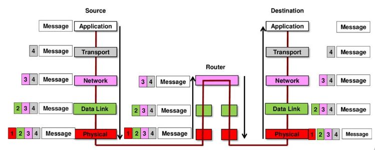
MESSAGE FORMAT AND ENCAPSULATION

The process of placing a message format (for example, a letter) into another message format (the envelope) is called encapsulation . When the recipient reverses this process and removes the letter from the envelope, the decapsulation occurs. Each computer message is encapsulated in a specific format, called a frame (the envelope in the letter example), before being sent over the network.

 MESSAGE SIZE

Frame size restrictions require the source host to divide a long message into individual fragments that meet the minimum and maximum size requirements. The long message will be sent in independent frames, each frame will contain a part of the original message. Each frame will also have its own addressing information. On the receiving host, the messages are decapsulated and rejoined for processing and interpretation.

MESSAGE SYNCHRONIZATION
The three elements are taken into account: Access method, Flow control and Timeout for the response. The Access Method determines when a device can send a message; the  flow control determines the amount of information that can be sent and the speed with which it can be delivered and; The Timeout for the response specifies how long they should wait for an answer and what to do if it runs out.

MESSAGE DELIVERY OPTIONS

A message can be delivered in different ways:

  • Unicast (Multicast)
  • Multicast (Multicast) 
  •  Broadcast (Broadcast)


A one-to-one delivery option is called "unicast," which means that the message has only one recipient. If a host needs to send messages to several at the same time, it is called "multicasting." If it is necessary for all hosts on the network to receive the message at the same time, the broadcast method is used.

Cisco NETWORK PROTOCOLS

The protocols define the format and structure of the message that the devices exchange. Some examples of the most common network protocols are Hypertext Transfer Protocol (HTTP), the transmission control protocol (TCP) and the Internet protocol (IP).

TCP / IP PROTOCOL SUITE or Model

TCP / IP protocols are specific to the Application, Transport and Internet layers . The protocols of the network access layer are responsible for the delivery of IP packets on physical media and are developed by standardization organizations, such as IEEE.
Table of the TCP / IP Protocol Set.
ProtocolDescription
DNSTranslate domain names such as ccnacompletecourse.blogspot.com to an IP addresses
DHCPAssign IP addresses dynamically to counting stations when started and allow addresses to be reused when they are no longer needed
BOOTPEnable a diskless workstation to discover its own IP address, the IP address of a BOOTP server on the network and a file that must be loaded into memory to start the machine.
IMAPAllows customers to access emails stored on a mail server
POPAllows customers to retrieve an email from a mail server
SMTPAllow customers to send an email to a mail server
FTPSets the rules that allow a user on a host to access and transfer files to and from another host on a network
TFTPA file delivery protocol without acknowledgment of great effort that uses less overhead than FTP.
HTTPSet of rules for exchanging text, graphic images, sound, video and other multimedia files on the World Wide Web
UDPEnable a process that runs on one host to send packets to a process that runs on another host
TCPIt allows reliable communication between processes running on independent hosts
IPRoute packages for complete training through an intemetwork
NATTranslate IP addresses from a private network to unique public IP addresses globally
ICMPProvide comments from a destination host to a source host regarding packet delivery errors
OSPFLink-State Routing Protocol
EIGRPCisco Exclusive Routing Protocol
ARPProvides dynamic address assignment between an IP address and a hardware address
PPPIt provides a means of encapsulating packets to transmit them through a serial link
EthernetDefine the rules for connecting and signaling network access layer standards
Internet controllersProvides instructions to the machine to control a specific interface on a network device

NETWORK STANDARDS ORGANIZATIONS

Open standards ensure that no single company product can monopolize the market or have an unfair advantage over the competition. For example, they allow a client with the Apple OS X operating system to download a web page from a web server with the Linux operating system. This is because both operating systems implement the open standard protocols, such as those in the TCP / IP suite.

INTERNET STANDARDS

Different organizations have different responsibilities to promote and develop standards for the TCP / IP protocol. With regard to the Internet we have:


  • Internet Engineering Working Group (IEFT) : develops, updates and maintains Internet and TCP / IP technologies. This includes documentation for the development of new protocols and the updating of existing protocols, known as comment request documents (RFCs).
  • Internet Society (ISOC) : is responsible for promoting the open development, evolution and use of the Internet worldwide.
  • Internet Corporation for Assigned Names and Numbers (ICANN) : based in the United States, it coordinates the assignment of IP addresses, the administration of domain names and the assignment of other information used by the TCP / IP protocols.
  • Internet Architecture Council (IAB) : is responsible for the administration and general development of Internet standards.
  • Internet Research Working Group (IRTF) : is focused on long-term research in relation to Internet and TCO / IP protocols.
  • Internet Assigned Numbers Authority (IANA) : responsible for supervising and administering IP address assignment, domain name management and protocol identifiers for ICANN.

ORGANIZATIONS OF STANDARDS FOR COMMUNICATIONS AND ELECTRONICS

They have responsibilities for the promotion and creation of standards that are used in the delivery of IP packets such as electronic signals in wireless or cable media. And we have:


  • Institute of Electrical and Electronics Engineers (IEEE) : Dedicated to advancing technological innovation and developing standards in a wide range of sectors, including energy, health services, telecommunications and networks.
  • Electronic Industries Association (EIA) : standards related to electrical wiring, connectors and racks 19.
  • Association of Telecommunications Industries (TIA) : communication standards including radio equipment, mobile phone towers, voice over IP (VoIP) devices, satellite communications and more.
  • Telecommunication Standardization Sector of the International Telecommunication Union (ITU-T) : Defines standards for video compression, Internet protocol television (IPTV) and broadband communications, such as the digital subscriber line (DSL).
  • Among some known standards we have  IEEE 802.3 , which defines the media access control (MAC) for wired Ethernet and IEEE 802.11 , which defines a set of standards for implementing wireless local area networks (WLAN).

I hope this informative for your, thank you for visiting here.!


Friday 16 August 2019

Basic Configuration of Cisco Router and Switch

Basic Configuration of Cisco Router and Switch

This is article is about the Basic Configuration of Cisco Router and Switch. You will learn step by step how to start configuring the Cisco Router and Switch. We will start to learn the basic configuration of Cisco devices. We will take as an example the configuration of a Switch, but the commands work the same way for a Router. Before going into configurations, you must aware with the basic mode of configuration on Cisco Router.

How to configure Hostname on Cisco Devices:

To name the device you must enter the hostname command and to remove the configured hostname and return to the default input request, use the global non-
hostname configuration command . This is how we configure it on the console:

Switch> Switch> enable 
Switch # 
configure terminal Enter configuration commands, one per line. End with CNTL / Z. 
Switch (config) #hostname Sw-Floor-1 
Sw-Floor-1 (config) # Sw-Piso-1 
(config) #no hostname 
Switch (config) #


For setting the hostname on cisco devices, you should consider the following:

  • It must start with a letter
  • It must not contain spaces
  • It ends with a letter or a digit
  • Only letter, digits and hyphens are used
  • Must be less than 64 characters in length

How to set the different passwords on Cisco Devices:

DEVICE ACCESS PROTECTION


  • Protect access to EXEC modes with privileges and user EXEC with a password.

Enable password on Cisco Router:
The enable secret command provides greater security because the password is encrypted. Let's see how to do it on the console:

Switch>Switch> enable
Switch # conf terminal
Enter configuration commands, one per line. End with CNTL / Z.
Switch (config) #enable secret cisco
Switch (config) #exit

My password is  cisco, and if I go out ( exit ) to return to privileged mode, it will ask me to enter the password.
Switch # exit
Switch> enable
Password:
  • Protect virtual terminal lines with a password
Console password on Cisco Router:

Security must be provided to the console port. This reduces the chances of unauthorized personnel physically connecting a cable to the device and accessing it. We configure it as follows with password ccna_cisco
Switch # conf t
Switch (config) #line console 0
Switch (config-line) #password ccna_cisco
Switch (config-line) #login
Switch (config-line) #exit
Telnet password on Cisco Router:

The vty lines allow access to a Cisco device through Telnet or SSH. The number of vty lines supported varies by device type and IOS version. Of course we must protect them with password and do as follows with password ccna_cisco
Switch # conf t
Switch (config) #line vty 0 15
Switch (config-line) #password ccna_cisco
Switch (config-line) #login

How to ENCRYPT Your password on Cisco?


  • Cisco IOS shows passwords in plain text by default.
  • Passwords must be encrypted.

The service password-encryption command prevents passwords from appearing as unencrypted text when the configuration is displayed. The purpose of this command is to prevent unauthorized people from seeing the passwords in the configuration file.

This is how passwords appear before executing the command:
Switch # show running-config 
Building configuration ...
....
line with 0
 password Cisco
 login
!
line vty 0 4
 password ccna_cisco
 login
line vty 5 15
 password ccna_cisco
 login
And this is how passwords appear after executing the command:
Switch # conf t
Switch (config) #service password-encryption
Switch # show running-config 
Building configuration ...
...
line with 0
 password 7 0822408008
 login
!
line vty 0 4
 password 7 08FF4140081C0004160F0F01FFFF
 login
line vty 5 15
 password 7 08FF1141181C0004160F0F01FFFF

 login

CISCO DEVICE CONFIGURATION: SAVE CONFIGURATION

Finally, once the basic configuration of the IOS devices is done, we will save the configuration. First let's look at the two system files that store the device configuration:
  • startup-config : the file stored in non-volatile random access memory (NVRAM) that contains all the commands that the device will use during startup or restart. NVRAMmemory does not lose its content when the device disconnects.
  • running-config : the file stored in random access memory (RAM) that reflects the current configuration. Modifying a running configuration affects the operation of a Cisco device immediately. RAM is volatile . It loses all content when the device shuts down or restarts.
Then, to save the configuration, we "copy" the "execution" file to the "initialization" file, as follows:
Switch # copy running-config startup-config
Final Considerations:
  • If the changes made to the running configuration do not have the desired effect and the running-config file has not yet been saved, you can restore the initial configuration with the reload command .
Switch # reload
Proceed with reload? [confirm]
  • Also, if you want to delete the startup configuration use the erase startup-config command
Switch # erase startup-config 
Erasing the nvram filesystem will remove all configuration files! Continue? [confirm]
[OKAY]
Erase of nvram: complete
% SYS-7-NV_BLOCK_INIT: Initialized the geometry of nvram
Switch #
  • Finally, on a switch the command delete vlan.dat must also be issued
Switch # delete vlan.dat
Delete filename [vlan.dat]?
Delete flash: /vlan.dat? [confirm]
% Error deleting flash: /vlan.dat (No such file or directory)

How to Configure IP address on Cisco Router:

Following command will the set the IP address 176.6.32.1 on interface f0/0.
 switch(config)#interface f0/0
Router(config)# ip address 176.6.32.1 255.255.255.0
Router(config-int)# no shutdown 

Shutdown command will change the status of interface fo/o to active.