RIP Configuration on Cisco Router | RIP Lab
This post will help you in learning how to enable and RIP configuration on Cisco Router. Although the RIP protocol is used very rarely in modern networks, it is useful as a basis for understanding basic network routing. This section provides a brief overview of the way in which basic RIP values are configured and how RIPv2 is verified.RIP Configuration Mode
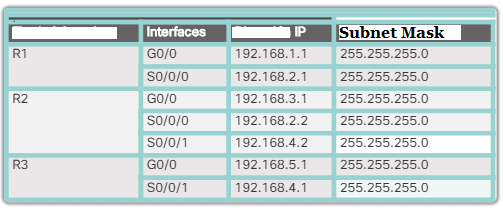
In following figure, all routers were configured with basic administration functions, and all interfaces identified in the reference topology are configured and enabled. There are no static routes configured or routing protocols enabled, so remote network access is impossible at that time.
RIPv1 is used as a dynamic routing protocol. To enable RIP, use the router rip command, as shown below:
R1 # conf t

Enter configuration commands, one per line. End with CNTL / Z.

R1 (config) # router rip

R1 (config-router) #
This command does not directly initiate the RIP process. Instead, it provides access to the router configuration mode, where RIP routing parameters are configured. When RIP is enabled, the default version is RIPv1.To disable and remove RIP, use the global no router rip configuration command . This command stops the RIP process and removes all existing RIP configurations.
Upon entering the RIP router configuration mode, the router is instructed to run RIPv1 . But the router still needs to know the local interfaces that it must use to communicate with other routers, as well as the locally connected networks that it must publish to those routers.
To enable RIP routing for a network, use network network address (router configuration mode command) Enter the classy network address for each directly connected network.
Taking into account the previous example, we will announce the networks directly connected to R1, R2 and R3.
R1 (config) # router rip

R1 (config-router) # network 192.168.1.0

R1 (config-router) # network 192.168.2.0

R1 (config-router) #

R2 (config) # router rip

R2 (config-router) # network 192.168.2.0

R2 (config-router) # network 192.168.3.0

R2 (config-router) # network 192.168.4.0

R3 (config) # router rip

R3 (config-router) # network 192.168.4.0

R3 (config-router) # network 192.168.5.0
These commands does the following:
- Enable RIP on all interfaces that belong to a specific network. Makes the associated interfaces now send and receive RIP updates.
- Publish the specified network in RIP routing updates sent to other routers every 30 seconds.
Verify the RIP Configuration on Cisco Router:
The show ip protocols command shows the IPv4 routing protocol parameters currently configured on the router. This result is shown below and confirms most of the RIP parameters, including the following:- RIP routing is configured and running on router R1.
- The values of various timers; for example, R1 sends the next routing update in 16 seconds.
- The currently configured version of RIP is RIPv1.
- R1 summarizes at the limit of the classy network.
- R1 announces classy networks. These are the networks that R1 includes in its RIP updates.
- RIP neighbors are indicated by the inclusion of the IP address of the next hop, the associated AD that R2 uses for updates sent by that neighbor, and when that neighbor received the last update.
R1 # show ip protocols
The command show ip routeshows the RIP routes installed in the routing table. We verify that R1 now has information about the highlighted networks.
R1 # show ip route | begin gateway
Gateway of last resort is not set

192.168.1.0/24 is variably subnetted, 2 subnets, 2 masks
C 192.168.1.0/24 is directly connected, GigabitEthernet0 / 0
L 192.168.1.1/32 is directly connected, GigabitEthernet0 / 0
 192.168.2.0/24 is variably subnetted, 2 subnets, 2 masks
C 192.168.2.0/24 is directly connected, Serial0 / 0/0
L 192.168.2.1/32 is directly connected, Serial0 / 0/0
R 192.168.3.0/24 [120/1] via 192.168.2.2, 00:00:24, Serial0 /
0/0 R 192.168.4.0/24 [120/1] via 192.168.2.2, 00:00:24, Serial0 /
0/0 R 192.168.5.0/24 [120/2] via 192.168.2.2, 00:00:24, Serial0 / 0/0
R1 #
How to enable RIP V2 On Cisco Router
By default, when a RIP process is configured on a Cisco router, it runs RIPv1. However, even though the router only sends RIPv1 messages, it can interpret RIPv1 and RIPv2 messages. RIPv1 routers simply ignore RIPv2 fields in the route entry.
Use the router version 2 configuration mode command to enable RIPv2:
R1 (config) # router rip
R1 (config-router) # version 2
R1 (config-router) # ^ Z
R1 #
R1 # show ip protocols | Default section
 Default version control: send version 2, receive version 2
 Interface Send Recv Triggered RIP Key-chain
 GigabitEthernet0 / 0 2 2
 Serial0 / 0/0 2 2
R1 #
Notice how the show ip protocols command verifies that R2 is now configured to send and receive only version 2 messages. The RIP process now includes the subnet mask in all updates, which makes RIPv2 a protocol. Routing without class .
Next, it is verified that there are no longer RIP routes in the routing table. This is because R1 is now listening for RIPv2 updates only. R2 and R3 still send RIPv1 updates. Therefore, the version 2 command must be configured on all routers in the routing domain.
R1 # show ip route | begin gateway
Gateway of last resort is not set

192.168.1.0/24 is variably subnetted, 2 subnets, <br> 2 masks
C 192.168.1.0/24 is directly connected,
GigabitEthernet0 / 0
L 192.168.1.1/32 is directly connected,
GigabitEthernet0 / 0
 192.168.2.0/24 is variably subnetted, 2 subnets,
2 masks
C 192.168.2.0/24 is directly connected, Serial0 / 0/0
L 192.168.2.1/32 is directly connected, Serial0 / 0/0
R1 #
5. DISABLE AUTO SUMMARY
As shown in the following result, RIPv2 automatically summarizes networks in the main network limits by default, as does RIPv1.
R1 # show ip protocols
*** IP Routing is NSF aware ***

Routing Protocol is "rip"
 Outgoing update filter list for all interfaces is not set
 Incoming update filter list for all interfaces is not set
 Sending updates every 30 seconds, next due in 16 seconds
 Invalid after 180 seconds, hold down 180, flushed after
 240
 Redistributing: rip
 Default version control: send version 2, receive version 2
 Interface Send Recv Triggered RIP Key-chain
 GigabitEthernet0 / 0 1 1 2
 Serial0 / 0/0 1 1 2
Automatic network summarization is in effect
 Maximum path: 4
 Routing for Networks:
 192.168.1.0
 192.168.2.0
 Routing Information Sources:
 Gateway Distance Last Update
 192.168.2.2 120 00:00:15
 Distance: (default is 120)
R1 #
To modify the default RIPv2 automatic summarization behavior, use the router configuration mode command not auto-summary , as shown:
R1 (config) # router rip
R1 (config-router) # no auto-summary
R1 (config-router) # end
R1 #
* Mar 10 14: 11: 49.659:% SYS-5-CONFIG_I: Configured from
console by console
R1 # show ip protocols | Automatic section
 Automatic network summarization is not in effect
R1 #
This command has no effect when RIPv1 is used. When automatic summarization is disabled, RIPv2 no longer summarizes the networks to its classy address on border routers. RIPv2 now includes all subnets and their corresponding masks in their routing updates. The show ip protocols command now indicates the following: automatic network summarization is not in effect (the automatic network summary is not in effect).
RIP Passive Interface Configurations on Cisco Router
By default, RIP updates are forwarded across all interfaces with RIP enabled. However, RIP updates should only be sent via interfaces connected to other routers with RIP enabled .
For example, see the topology in the example figure. RIP sends updates via its G0 / 0 interface, although there is no RIP device on that LAN. There is no way for R1 to have information about this and, as a result, it sends an update every 30 seconds. Sending unnecessary updates to a LAN impacts the network in three ways:
- Waste bandwidth : Bandwidth is used to transport unnecessary updates. Since RIP updates are transmitted by broadcast or multicast, the switches also resend the updates through all ports.
- Waste of resources : all devices on the LAN must process the update to the transport layers, at which point the devices discard the update.
- Security risk : the announcement of updates on a broadcast network constitutes a security risk. RIP updates can be intercepted with protocol analyzer software. Routing updates can be modified and sent back to the router, and damage the routing table with false metrics that disorient traffic.
It is not necessary for R1, R2, and R3 to forward RIP updates over their LAN interfaces. In the following configuration, the G0 / 0 interface of R1 is identified as passive. The show ip protocols command is used to verify that the Gigabit Ethernet interface is passive. Note that it is no longer indicated that the G0 / 0 interface sends or receives version 2 updates, but is found in the Passive Interface (s) section . Also, note that the 192.168.1.0 network is still under Routing for Networks , which means that this network is still included as a route entry in the RIP updates that are sent to R2.
R1 (config) # router rip

R1 (config-router) # passive-interface g0 / 0

R1 (config-router) # end

R1 #

R1 # show ip protocols | begin Default

Default version control: send version 2, receive version 2

Interface Send Recv Triggered RIP Key-chain

Serial0 / 0/0 2 2

Automatic network summarization is not in effect

Maximum path: 4

Routing for Networks:

192.168.1.0

192.168.2.0

Passive Interface (s):

GigabitEthernet0 / 0

Routing Information Sources:

 Gateway Distance Last Update

 192.168.2.2 120 00:00:06

Distance: (default is 120)

R1 #
Note : All routing protocols support the passive-interface command.Alternatively, all interfaces can be made passive with the passive-interface default command . Interfaces that must not be passive can be re-enabled with the no passive-interface command .
Propagation of a default route:
In following figure, R1 is the perimeter router with a simple connection to a service provider. Therefore, for R1 to reach the Internet, only a default static route from the Serial 0/0/1 interface is required.

Similar predetermined static routes could be configured on R2 and R3, but it is much more scalable to enter it once on perimeter router R1 and then make R1 propagate it to the rest of the routers using RIP. To provide Internet connectivity to all other networks in the RIP routing domain, the default static route must be published to all other routers that use the dynamic routing protocol.
To propagate a default route in RIP, the perimeter router must be configured with the following:
- A default static route, using the ip route 0.0.0.0 0.0.0.0 command .
- The default-information originate router configuration command . This instructs R1 to produce default information by propagating the default static route in RIP updates.
Finally, let's configure a completely specified default static route to the service provider and then the route is propagated using RIP. Note that R1 now has a gateway of last resort and a default route installed in its routing table.
R1 (config) # ip route 0.0.0.0 0.0.0.0 S0 / 0/1 209.165.200.226
R1 (config) # router rip
R1 (config-router) # default-information originate
R1 (config-router) # ^ Z
R1 #
* Mar 10 23: 33: 51.801:% SYS-5-CONFIG_I: Configured from
console by console
R1 # show ip route | begin gateway
Gateway of last resort is 209.165.200.226 to network 0.0.0.0

S * 0.0.0.0/0 [1/0] via 209.165.200.226, Serial0 / 0/1
 192.168.1.0/24 is variably subnetted, 2 subnets, 2 masks
C 192.168.1.0/24 is directly connected, GigabitEthernet0 / 0
L 192.168.1.1/32 is directly connected, GigabitEthernet0 / 0
 192.168.2.0/24 is variably subnetted, 2 subnets, 2 masks
C 192.168.2.0/24 is directly connected, Serial0 / 0/0
L 192.168.2.1/32 is directly connected, Serial0 / 0/0
R 192.168.3.0/24 [120/1] via 192.168.2.2, 00:00:08,
Serial0 / 0/0
R 192.168.4.0/24 [120/1] via 192.168.2.2, 00:00:08,
Serial0 / 0/0
R 192.168.5.0/24 [120/2] via 192.168.2.2, 00:00:08,
Serial0 / 0/0
 209.165.200.0/24 is variably subnetted, 2 subnets, 2 masks
C 209.165.200.0/24 is directly connected, Serial0 / 0/1
L 209.165.200.225/27 is directly connected, Serial0 / 0/1
R1 #
No comments:
Post a Comment