How to Configure Vlan On Cisco Router
This section describes How to Configure Vlan On Cisco Router and
VLAN trunks. In post is specifically related to configuration of VLAN, if you
want to learn about what is the VLAN you can
visit the previous post.
Table of Contents
- VLAN ranges on Catalyst switches
- Creation of a VLAN
- Assignment of ports to VLAN networks
- How to Delete a VLan
- Verification of VLAN information
- VLAN Trunks Configuration
- VLAN Troubleshooting
- Troubleshooting trunks configurations
How many VLANs you can configure on Cisco Switch
Different Cisco Catalyst switches support various amounts of VLAN.
The amount of VLANs they support is sufficient to meet the needs of most
organizations. For example, the Catalyst 2960 and 3560 series switches support
more than 4000 VLANs. The normal range VLANs on these switches are numbered
from 1 to 1005, and the extended range VLANs are numbered from 1006 to 4094.
The following illustration shows the available VLANs on a Catalyst 2960 switch
running Cisco IOS, version 15.x.
Normal Range VLAN
·
It is used in networks of small
and medium businesses and companies.
·
It is identified by a VLAN ID
between 1 and 1005.
·
IDs from 1002 to 1005 are reserved
for Token Ring VLANs and fiber optic distributed data interface (FDDI).
·
IDs 1 and 1002 to 1005 are created
automatically and cannot be deleted.
·
The settings are stored in a VLAN
database file, called vlan.dat. The vlan.dat file is located in the flash
memory of the switch.
·
The VLAN trunk link protocol
(VTP), which allows you to manage VLAN settings between switches, can only
discover and store VLAN networks of normal range.
Extended VLAN Range
·
It enables service providers to
expand their infrastructure to a larger number of customers. Some global
companies may be large enough to need the IDs of extended range VLANs.
·
They are identified by a VLAN ID
between 1006 and 4094.
·
The settings are not written to
the vlan.dat file.
·
They support fewer VLAN features
than normal range VLANs.
·
They are saved, by default, in the
running configuration file.
·
VTP does not learn extended range
VLANs.
How to create VLAN on Cisco Switch
When configuring VLAN networks of normal range, the configuration details are stored in the flash memory of the switch in a file called vlan.dat. The flash memory is persistent and does not require the copy running-config startup-config command. However, because other details are usually configured on Cisco switches at the same time that VLANs are created, it is advisable to save the changes to the running configuration in the startup configuration. The following table shows the syntax of the Cisco IOS command that is used to add a VLAN to a switch and assign it a name. It is recommended to name each VLAN in the configuration of a switch.|
Description
|
Command
|
|
Enter global
configuration mode.
|
S1 # configure terminal
|
|
Create a VLAN with a
valid ID number.
|
S1 (config) #vlan id-vlan
|
|
Specify a unique name to
identify the VLAN.
|
S1 (config-vlan) #name
vlan-name
|
|
Return to privileged EXEC
mode.
|
S1 (config-vlan) # end
|
|
Table of Commands for Creating a VLAN.
|
|
VLAN Configuration Example
In following figure, it is
shown how VLAN is configured for students (VLAN 20) on switch S1. In the
topology example, the student's computer (PC2) has not yet been associated with
any VLAN, but has the IP address 172.17.20.22.

S1# configure terminal
S1(config)# vlan 20
S1(config-vlan)# name student
S1(config-vlan)# end

The switchport
access vlan command forces the creation of a VLAN if
it does not already exist on the switch. For example, VLAN 30 is not
present in the result of the show vlan brief command of
the switch. If the switchport access vlan 30 command is
entered on any interface without prior configuration, the
switch displays the following:
% Access VLAN does not exist. Creating vlan 30
How change the membership
of Port of VLAN
There are several ways to
change the membership of ports in a VLAN. The following table shows the
syntax for changing the membership of a switch port of VLAN 1 with
the no switchport access vlan command of the interface configuration
mode.
|
Description
|
Command
|
|
Enter global
configuration mode.
|
S1 # configure terminal
|
|
Remove the VLAN
assignment from the port.
|
S1 (config-if) # no
switchport access vlan
|
|
Return to privileged
EXEC mode.
|
S1 (config-if) # end
|
|
VLAN
Assignment Elimination Table.
|
|
CONFIGURATION EXAMPLE

VERIFICATION EXAMPLE

ASSIGNING A PORT TO A VLAN
The VLAN membership of a port can be easily changed. It is not necessary to first remove a port from a VLAN to change its VLAN membership. When the VLAN membership of an access port is reassigned to another existing VLAN, the new VLAN membership simply replaces the previous VLAN membership. Next, port F0 / 11 was assigned to VLAN 20.
S1 # config t
S1 (config) # interface F0 / 11
S1 (config-if) # switchport mode access
S1 (config-if) # switchport access vlan 20
S1 (config-if) # end
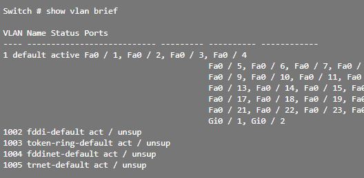
How to delete a VLAN
In the illustration, the global configuration mode command no vlan id-vlan is used to remove VLAN 20 from the switch. Switch S1 had a minimal configuration with all ports in VLAN 1 and an unused VLAN 20 in the VLAN database. The show vlan brief command verifies that VLAN 20 is no longer present in the vlan.dat file after using the no vlan 20 command.
S1 # conf t
S1 (config) # no vlan 20
S1 (config) # end
Caution: Before deleting a VLAN, reassign all member ports to a different
VLAN. Ports that do not transfer to an active VLAN cannot communicate with
other hosts once the VLAN is removed and until they are assigned to an active
VLAN.Alternatively, the entire vlan.dat file can be deleted with the delete flash command: vlan.dat in the privileged EXEC mode. The abbreviated version of the command (delete vlan.dat) can be used if the vlan.dat file was not moved from its default location. After issuing this command and reloading the switch, the previously configured VLANs are no longer present. This returns the switch to the factory default condition with respect to the VLAN configuration.
VERIFICATION OF VLAN INFORMATION
Once a VLAN is configured, the configuration can be validated with the Cisco IOS show commands.show vlan [ brief | id id-vlan | name vlan-name | summary ]
The
following table shows the options for the show vlan and show interfaces commands .
|
Description
|
Command
|
|
Show a line for each VLAN with its name,
status and ports.
|
brief
|
|
Show information about a single VLAN
identified by its ID number.
For the vlan-id, the range is 1 to 4094. |
id id-vlan
|
|
Show information about a single VLAN
identified by name. The name of the VLAN is an ASCII string of 1 to 32
characters.
|
name vlan-name
|
|
Show the summary of VLAN information.
|
summary
|
|
Show vlan command table
|
|
USE THE SHOW VLAN COMMAND

USE THE SHOW INTERFACES VLAN COMMAND
The show interfaces vlan id-vlan command shows details that exceed the scope of this course. The important information appears on the second line of the following scheme, which indicates that VLAN 20 is active.
VLAN TRUNKS CONFIGURATION
A VLAN trunk link is a layer 2 link of the OSI model between two switches that carries traffic for all VLANs (unless the list of allowed VLANs is restricted manually or dynamically). To enable trunk links, configure the ports at either end of the physical link with parallel command sets. To configure a switch port at one end of a trunk link, use the switchport mode trunk command. With this command, the interface switches to permanent trunk mode. The port establishes a dynamic trunk link protocol (DTP) negotiation to convert the link into a trunk link, even if the interface connected to it does not accept the change. In this course, the switchport mode trunk command is the only method that is implemented for trunking configuration.The following table shows the syntax of the Cisco IOS command to specify a native VLAN (other than VLAN 1). In the example, VLAN 99 is configured as a native VLAN with the switchport trunk native vlan 99 command.
|
Description |
Command |
|
Enter
global configuration mode. |
S1 #
configure terminal |
|
Enter the
interface configuration mode. |
S1 (config)
# interface interface_id |
|
Make the
link a trunk link. |
S1
(config-if) # switchport mode trunk |
|
Specify a
native VLAN for frames without labels. |
S1
(config-if) # switchport trunk native vlan id_vlan |
|
Specify the
list of VLANs that will be allowed on the trunk link. |
S1
(config-if) # switchport trunk allowed vlan vlan-list |
|
Return to
privileged EXEC mode. |
S1
(config-if) # end |
|
Trunk
Link Configuration Table |
|
VLAN TOPOLOGY EXAMPLE
In following image, VLANs 10, 20 and 30 support the Teaching, Student and Guest computers (PC1, PC2 and PC3). Port F0 / 1 of switch S1 was configured as a trunk link port and forwards traffic for VLANs 10, 20 and 30. VLAN 99 was configured as a native VLAN.

VLAN 10 - Faculty / Staff - 172.17.10.0/24
VLAN 20 - Students - 172.17.20.0/24
VLAN 30 - Guest - 172.17.30.0/24
VLAN 99 - Native - 172.17.99.0/24
The following
shows the configuration of port F0 / 1 of switch S1 as a trunk link port. The
native VLAN is changed to VLAN 99 and the list of allowed VLANs is restricted
to 10, 20, 30 and 99.
S1 (config) # interface FastEthernet0 / 1
S1 (config-if) # switchport mode trunk
S1 (config-if) # switchport trunk native vlan 99
S1 (config-if) # switchport trunk allowed vlan
10,20,30,99
S1 (config-if) # end
RESET THE TRUNK LINK TO THE DEFAULT STATE
The following table shows the commands to remove the allowed VLANs and restore the native VLAN from the trunk. When it is restored to the default state, the trunk link allows all VLANs and uses VLAN 1 as a native VLAN.|
Description |
Command |
|
Enter
global configuration mode. |
S1 #
configure terminal |
|
Enter the
interface configuration mode. |
S1 (config)
# interface interface_id |
|
Establish
the trunk link to allow all VLANs. |
S1
(config-if) # no switchport trunk allowed vlan |
|
Reset the
native VLAN to the default value. |
S1
(config-if) # no switchport trunk native vlan |
|
Return to
privileged EXEC mode. |
S1
(config-if) # end |
|
Reset
table of values configured in trunks |
|


TRUNK LINK CONFIGURATION VERIFICATION
The following result shows the configuration of port F0 / 1 of switch S1. The configuration is verified with the command show interfaces id-switchport interface.

VLAN TROUBLESHOOTING

The verification of the IPv4 configuration options of PC1, which is shown in the following result, reveals the most frequent error in the configuration of VLAN networks: a badly configured IPv4 address. PC1 was configured with IPv4 address 172.172.10.21, but should have been configured with address 172.17.10.21.

PC1>
ipconfig
IP
Address ...................: 172.172.10.21
Subnet
Mask ..................: 255.255.0.0
Default Gateway ..............:
0.0.0.0
The PC1 Fast Ethernet configuration dialog box shows the updated IPv4 address, 172.17.10.21. The result shown at the bottom indicates that PC1 regained connectivity to the Web / TFTP server located at IPv4 address 172.17.10.30.
PC1> ping 172.17.10.30
Pinging 172.17.10.30 with 32
bytes of data:
Reply from 172.17.10.30: Bytes
= 32 Time = 147ms TTL = 128
How to Troubleshoot MISSING VLANS
If there is still no connection between the devices in a VLAN but the IP addressing problems have been ruled out.Step 1 : Use the show vlan command to verify if the port belongs to the expected VLAN. If the port was assigned to an incorrect VLAN, use the switchport access vlan command to correct VLAN membership. Use the show mac address-table command to review which addresses were obtained on a particular port on the switch and to which VLAN that port was assigned, as shown below:


TROUBLESHOOTING TRUNKS
One of the common tasks of network administrators is to solve problems of trunk or port link formation that behaves incorrectly as trunk ports. Occasionally, a switch port may behave as a trunk link port, even if it was not configured as such. For example, an access port can accept frames from VLAN networks other than the VLAN to which it was assigned. This is known as "VLAN filtration."TROUBLESHOOTING COMMANDS
To solve problems of trunk links that are not formed or VLAN filtering, proceed as follows:
·
Step 1 : Use the show interfaces
trunk command to verify if there is a
match between the local native VLAN and the peers. If the native VLAN does not
match at both ends, there is a VLAN leak.
·
Step 2 : Use the show interfaces
trunk command to verify if a trunk link
was established between the switches. Staticly configure trunks whenever
possible. Cisco Catalyst switch ports use DTP by default and attempt to
negotiate a trunk.
To show the
status of the trunk link and the native VLAN used in it, and verify the
establishment of that link, use the show interfaces trunk command . Next, it is shown that the native VLAN at
one end of the trunk link was changed to VLAN 2. If one end of the trunk link
is configured as native VLAN 99 and the other end as native VLAN 2, the frames
that are sent from the trunk VLAN 99 on one end are received on VLAN 2 on the other
end. VLAN 99 is filtered in segment VLAN 2.
SW1 # show interfaces f0 / 1 trunk
Port Mode Encapsulation Status Native vlan
Fa0 / 1 car 802.1q
trunking 2
CDP displays
a native VLAN incompatibility warning on a trunk link with this message:
* Mar 1 06: 45: 26.232:% CDP-4-NATIVE_VLAN_MISMATCH:
Native VLAN mismatch discovered on FastEthernet0 / 1 (2), with S2 FastEthernet0
/ 1 (99).
If there is a
native VLAN incompatibility, connectivity problems occur on the network. Data
traffic for VLANs other than the two native VLANs configured is correctly
propagated through the trunk link, but data related to any of the native VLANs
is not propagated correctly through the trunk link.As shown above, the incompatibility problems of the native VLAN do not prevent the trunk link from forming. To resolve a native VLAN incompatibility, configure the native VLAN to be the same VLAN on both sides of the link.
COMMON ISSUES WITH TRUNKS
In general, trunk link problems are due to incorrect configuration. When configuring VLANs and trunks in a switched infrastructure, the most frequent configuration errors are as follows:
·
Incompatibility of native
VLAN: Trunk link ports were configured
with different native VLANs. This configuration error generates console notifications
and can cause routing problems between VLANs, among other inconveniences. This
represents a security risk.
For example,
one port is defined as VLAN 99 and the other as VLAN 100.
·
Incompatibilities of trunk
mode: A trunk port is configured in a
mode that is not compatible for trunk links on the corresponding peer port.
These configuration errors cause the trunk link to stop working. Ensure that
both sides of the trunk link are configured with the switchport mode trunk
command . The other trunk link
configuration commands exceed the scope of this course.
For example,
one side of the trunk link is configured as an access port.VLANs allowed on trunk links: The list of VLANs allowed on a trunk link with the current VLAN trunk requirements was not updated. In this case, unexpected traffic or no traffic is sent to the trunk link.
The list of allowed VLANs does not support the current VLAN trunk requirements.
If a problem with a trunk link is detected and the cause is unknown, start troubleshooting with a review of the trunk links to determine if there is a native VLAN incompatibility. If that is not the cause, check if there is a trunk link mode incompatibility and, finally, check the list of VLANs allowed on the trunk link. On the next two pages, we discuss how to troubleshoot frequent trunk links.
No comments:
Post a Comment