Showing posts with label vlan. Show all posts

Monday, 21 October 2019

NAT Types NAT Advantages and Disadvantages

NAT Types Advantages and Disadvantages

In this section, you will learn about the NAT Types , including static NAT, dynamic NAT and NAT with overload (PAT). We will discus about NAT advantages and disadvantages.

NETWORK ADDRESS TRANSLATION NAT Types 

There are three types of NAT translation:


  1. Static address translation (static NAT):  one-to-one address assignment between a local and a global address.
  2. Dynamic address translation (dynamic NAT):  Assignment of multiple addresses to various addresses between local and global addresses. Translations are made based on availability; for example: if there are 100 internal local addresses and 10 internal global addresses, then at a given time only 10 of the 100 internal local addresses can be translated. This dynamic NAT limitation makes it much less useful for production networks than port address translation.
  3. Port address translation (PAT):  Assigning multiple addresses to an address between local and global addresses. This method is also known as "overload" (NAT with overload). For example: if there are 100 internal local addresses and 10 internal global addresses, PAT uses the ports as an additional parameter to provide a multiplier effect, allowing any of the 10 internal global addresses to be reused up to 65,536 times (depending on whether the flow is based in UDP, TCP or ICMP).

STATIC NAT

Static NAT consists of a one-to-one assignment between local and global addresses. These assignments are configured by the network administrator and remain constant.

In the illustration, R2 was configured with static assignments for the internal local addresses of Svr1, PC2 and PC3. When these devices send traffic to the Internet, their internal local addresses are translated to the configured internal global addresses. For external networks, these devices have public IPv4 addresses.
Static NAT is useful, especially for web servers or devices that must have a constant address that is accessible both from the Internet and from a company's web server. It is also useful for devices that authorized personnel should be able to access when they are not in their workplace, but not the general public on the Internet. For example, a network administrator can access the internal global address of Svr1 (209.165.200.226) from PC4 via SSH. R2 translates this internal global address to the internal local address and connects the administrator session to Svr1.
Static NAT requires that there be sufficient public addresses available to meet the total number of simultaneous user sessions.

DYNAMIC NAT

Dynamic NAT uses a set of public addresses and assigns them according to the order of arrival. When an internal device requests access to an external network, the dynamic NAT assigns a public IPv4 address available from the set.
In the illustration, PC3 accesses the Internet through the first available address of the dynamic NAT set. The other addresses are still available for use. Like static NAT, dynamic NAT requires that there be sufficient public addresses available to meet the total number of simultaneous user sessions.

PORT ADDRESS TRANSLATION (PAT)

The translation of the port address (PAT), also known as " NAT with overload ", assigns several private IPv4 addresses to a single public IPv4 address or to some addresses. This is what most home routers do. The ISP assigns an address to the router, but several family members can access the Internet simultaneously. This is the most common form of NAT.
With PAT, multiple addresses can be assigned to one or more addresses, because each private address is also tracked with a port number. When a device initiates a TCP / IP session, it generates a TCP or UDP source port value or a query ID specially assigned for ICMP, in order to identify the session without the possibility of ambiguities. When the NAT router receives a packet from the client, it uses its source port number to uniquely identify the specific NAT translation.
PAT guarantees that the devices use a different TCP port number for each session with an Internet server. When a response from the server arrives, the source port number, which becomes the destination port number on the return, determines to which device the router forwards the packets. The PAT process also validates that incoming packets have been requested, which adds a degree of security to the session.

 COMPARISON BETWEEN NAT AND PAT

As shown in the illustration, NAT translates IPv4 addresses into a 1: 1 ratio between private IPv4 addresses and public IPv4 addresses. However, PAT modifies the address and port number.
NAT forwards incoming packets to its internal destination using the input source IPv4 address provided by the host on the public network. In general, with PAT there are only one or very few publicly exposed IPv4 addresses. Incoming packets from the public network are routed to their destinations in the private network by consulting a table on the NAT router. This table tracks the pairs of public and private ports. This is called " connection tracking ."
What happens to IPv4 packets that carry data that are not TCP or UDP segments? These packets do not contain a layer 4 port number. PAT translates most of the common protocols transmitted through IPv4 that do not use TCP or UDP as the transport layer protocol. The most common of them is ICMPv4. PAT handles each of these types of protocols differently. For example, query messages, echo requests, and ICMPv4 echo responses include a query ID. ICMPv4 uses the query ID to identify an echo request with its respective response. The query ID increases with each echo request sent. PAT uses the query ID instead of a layer 4 port number.

BENEFITS OF NAT

NAT offers several benefits, including the following:


  • It retains the legally registered addressing scheme by allowing the privatization of intranets. NAT preserves the addresses by multiplexing applications at the port level. With NAT overloaded, internal hosts can share a single public IPv4 address for all external communications. In this type of configuration, very few external addresses are required to support multiple internal hosts.
  • Increase the flexibility of connections to the public network . Several backup and load balancing sets and sets can be implemented to ensure reliable public network connections.
  • NAT provides consistency to internal network addressing schemes . To change the public IPv4 address scheme on a network that does not use private IPv4 or NAT addresses, it is required to redirect all hosts on the existing network. The costs of redirecting hosts can be considerable. NAT allows to maintain the existing private IPv4 address scheme while facilitating the change to a new public addressing scheme. This means that an organization could change ISPs without modifying any of its internal clients.
  • NAT hides the IPv4 addresses of users . As it uses IPv4 RFC 1918 addresses, NAT provides the side effect of hiding the IPv4 addresses of users and other devices. Some people consider it a security feature, although most experts agree that NAT does not provide security. A firewall with status detection is what provides security to the perimeter of the network.

DISADVANTAGES OF NAT


  • NAT has some disadvantages. The fact that hosts on the Internet seem to communicate directly with the enabled NAT device, rather than with the real host within the private network, creates a number of drawbacks.
  • Network performance deteriorates , especially in the case of real-time protocols such as VoIP. NAT increases forwarding delays because the translation of each IPv4 address within packet headers takes time.
  • End-to-end addressing is lost . Many Internet protocols and applications depend on end-to-end addressing from source to destination. Some applications do not work with NAT. For example, some security applications, such as digital signatures, fail because the source IPv4 address changes before reaching its destination. Applications that use physical addresses, instead of a qualified domain name, do not reach the destinations that are translated through the NAT router. Occasionally, this problem can be avoided by implementing static NAT assignments.
  • IPv4 tracking is reduced from end to end . Tracking packages that go through several address changes through several NAT breaks becomes much more difficult and, consequently, makes troubleshooting difficult.
  • It causes complications in the use of tunneling protocols, such as IPsec, because NAT modifies values ​​in the headers, which causes integrity checks to fail.
  • The start of TCP connections can be interrupted . Unless the NAT router is configured to support such protocols, incoming packets cannot reach their destination. Some protocols may support a NAT instance between participating hosts (for example, passive FTP), but fail when NAT separates both systems from the Internet.


Wednesday, 16 October 2019

Inter Vlan Routing on Cisco | Routing between VLANs

Inter Vlan Routing on Cisco | Routing between VLANs 


A brief article on Inter Vlan Routing on Cisco or Routing between VLANs and sometimes know as router-on-a-stick routing. If you want to know what is Vlan and how to configure these vlans on Cisco Router, you can visit here.

Table of Contents

1. What is routing between VLANs?
2. Routing configuration between old VLAN
3. Configure a router on stick routing between VLANs

1. What is routing between VLANs?

VLANs are used to segment switched networks. Layer 2 switches, such as those of the Catalyst 2960 series, can be configured with more than 4000 VLANs. A VLAN is a broadcast domain , so computers in separate VLANs cannot communicate without the intervention of a routing device. Layer 2 switches have very limited functionality in IPv4 and IPv6, and cannot perform the dynamic routing functions of routers. While Layer 2 switches are increasingly acquiring IP functionality, such as the ability to perform static routing, this is not enough to address this large number of VLANs.
Any device that supports Layer 3 routing, such as a router or multilayer switch, can be used to achieve the necessary routing functionality. Regardless of the device used, the process of forwarding network traffic from one VLAN to another through routing is known as “routing between VLANs”.
There are three options for routing between VLANs:
  1. Routing between old VLAN
  2. Router on stick
  3. Layer 3 switching using SVIs

ROUTING BETWEEN OLD VLAN

Historically, the first solution for routing between VLANs used routers with several physical interfaces. It was necessary to connect each interface to a separate network and configure it for a different subnet.
In this old approach, routing between VLANs is done by connecting different physical interfaces of the router to different physical switch ports. The switch ports connected to the router are placed in access mode, and each physical interface is assigned to a different VLAN. Each router interface can then accept traffic from the VLAN associated with the switch interface that is connected and traffic can be routed to other VLANs connected to other interfaces.

THE EXAMPLE ROUTING BETWEEN OLD VLAN IS DESCRIBED 

  • PC1 in VLAN 10 communicates with PC3 in VLAN 30 through router R1.
  • PC1 and PC3 are on different VLANs and have IPv4 addresses on different subnets.
  • Router R1 has a separate interface configured for each of the VLANs.
  • PC1 sends the unicast traffic destined for PC3 to switch S2 on VLAN 10, from which it is then forwarded by the trunk interface to switch S1.
  • Switch S1 then forwards the unicast traffic through its F0 / 3 interface to the G0 / 0 interface of router R1.
  • The router routes unicast traffic through the G0 / 1 interface, which is connected to VLAN 30.
  • The router forwards unicast traffic to switch S1 on VLAN 30.
  • The switch S1 then forwards the unicast traffic to the switch S2 through the active trunk link, after which the switch S2 can forward the unicast traffic to the PC3 in the VLAN 30.
In this example, the router was configured with two separate physical interfaces to interact with the different VLANs and perform routing.

ROUTING BETWEEN VLANS WITH ROUTER-ON-A-STICK

Unlike routing between old VLANs, which requires several physical interfaces, both on the router and on the switch, the most common and current implementations of routing between VLANs do not have those requirements. Instead, some router softwares allow you to configure a router interface as a trunk link, which means that only one physical interface is necessary on the router and on the switch to route packets between several VLANs.
" Router-on-a-stick " is a type of router configuration in which a single physical interface routes traffic between several VLANs in a network. As can be seen in the illustration, the router is connected to switch S1 through a single physical network connection (a trunk link).
The router interface is configured to function as a trunk link and connects to a switch port configured in trunk mode. To perform routing between VLANs, the router accepts traffic with VLAN tags from the adjacent switch on the trunk interface and then routes it internally between the VLANs, using subinterfaces. The router forwards the routed traffic with VLAN tags to the destination VLAN through the same physical interface used to receive the traffic.
Subinterfaces are software-based virtual interfaces, associated with a single physical interface; they are configured in software on a router, and each subinterface is configured independently with an IP address and a VLAN assignment. Subinterfaces are configured for different subnets that correspond to your VLAN assignment to facilitate logical routing. After a routing decision is made according to the destination VLAN, the data frames receive VLAN tags and are sent back through the physical interface.

THE ROUTER-ON-A-STICK EXAMPLE IS DESCRIBED (IMAGE)

  • PC1 in VLAN 10 communicates with PC3 in VLAN 30 through router R1 through a single physical interface of the router.
  • PC1 sends unicast traffic to switch S2.
  • Then, switch S2 labels unicast traffic as originating in VLAN 10 and forwards it over the trunk link to switch S1.
  • Switch S1 forwards the traffic tagged by the other trunk interface on port F0 / 3 to the interface on router R1.
  • Router R1 accepts unicast traffic tagged on VLAN 10 and routes it to VLAN 30 through its configured subinterfaces.
  • Unicast traffic is tagged with VLAN 30 while sending through the router interface to switch S1.
  • Switch S1 forwards unicast traffic labeled by the other trunk link to switch S2.
  • Switch S2 removes the VLAN tag from the unicast frame and forwards the frame to PC3 on port F0 / 23.

2. Routing configuration between old VLAN

Routing between old VLANs requires that routers have multiple physical interfaces. The router performs routing by connecting each of its physical interfaces to a single VLAN. In addition, each interface is configured with an IPv4 address for the subnet associated with the specific VLAN to which it is connected. By configuring IPv4 addresses on the physical interfaces, network devices connected to each of the VLANs can communicate with the router through the physical interface connected to the same VLAN. In this configuration the network devices can use the router as a gateway to access the devices connected to the other VLANs.
The routing process requires the source device to determine if the destination device is local or remote from the local subnet. The source device makes this determination by comparing the source and destination IPv4 addresses with the subnet mask. Once it is determined that the destination IPv4 address is on a remote network, the source device must identify where it needs to forward the packet to reach the destination device. The source device examines the local routing table to determine where it is necessary to send the data. The devices use their default gateways as a Layer 2 destination for all traffic that the local subnet must leave.

PREPARATION

Once the source device determines that the packet must travel through the local router interface on the connected VLAN, it sends an ARP request to determine the MAC address of the local router interface. Once the router sends its ARP response to the source device, it can use the MAC address to finalize the packet framing before sending it to the network as unicast traffic.
Since the Ethernet frame has the destination MAC address of the router interface, the switch knows exactly to which port of the switch to forward the unicast traffic to reach the router interface of that VLAN. When the frame reaches the router, the router removes the information from the source and destination MAC address to examine the destination IPv4 address of the packet. The router compares the destination address with the entries in the routing table to determine where it is necessary to forward the data to reach the final destination. If the router determines that the destination network is a locally connected network, as would be the case with VLAN routing, it sends an ARP request through the interface that is physically connected to the destination VLAN. The destination device responds to the router with the MAC address, which then uses the router to pack the packet. The router sends unicast traffic to the switch, which forwards it through the port where the destination device is connected.
Although there are many steps in the VLAN routing process, when two devices in different VLANs communicate through a router, the entire process takes place in a fraction of a second.

SWITCH CONFIGURATION

To configure routing between old VLANs, start with the switch configuration.

As shown in Image 4, router R1 is connected to switch ports F0 / 4 and F0 / 5, which were configured for VLANs 10 and 30 respectively.
Use the global configuration command  vlan  vlan_id  to create the VLANs. In this example, VLANs 10 and 30 were created on switch S1.

S1 (config) # vlan 10
S1 (config-vlan) # vlan 30
S1 (config-vlan) # interface f0 / 11
S1 (config-if) # switchport access vlan 10
S1 (config-if) # interface f0 / 4
S1 (config-if) # switchport access vlan 10
S1 (config-if) # interface f0 / 6
S1 (config-if) # switchport access vlan 30
S1 (config-if) # interface f0 / 5
S1 (config-if) # switchport access vlan 30
S1 (config-if) # end </div>
* Mar 20 01: 22: 56.751:% SYS-5-CONFIG_I: Configured 
from console by console
S1 # copy running-config startup-config
Destination filename [startup-config]? 
Building configuration ...
[OKAY]
Once the VLANs are created, the switch ports are assigned to the appropriate VLANs. The switchport access vlan  id_de_vlan  command  is executed from the interface configuration mode on the switch for each interface to which the router is connected.
In this example, the F0 / 4 and F0 / 11 interfaces were assigned to VLAN 10 with the switchport access vlan 10 command  . The same process was used to assign interface F0 / 5 and F0 / 6 on switch S1 to VLAN 30.
Finally, to protect the configuration and not lose it after a reload of the switch, the copy running-config startup-config command is executed   to save a backup copy of the running configuration in the startup configuration.

ROUTER INTERFACE CONFIGURATION

You can then configure the router to perform routing between VLANs.
Router interfaces are configured similarly to VLAN interfaces on switches. To configure a specific interface, enter interface configuration mode from global configuration mode.

R1 (config) # interface g0 / 0 
R1 (config-if) # ip address 172.17.10.1 255.255.255.0 
R1 (config-if) # no shutdown
* Mar 20 01: 42: 12.951:% LINK-3-UPDOWN: Interface 
GigabitEthernet0 / 0, changed state to up
* Mar 20 01: 42: 13.951:% LINEPROTO-5-UPDOWN: Line protocol on
Interface GigabitEthernet0 / 0, changed state to up
R1 (config-if) # interface g0 / 1 
R1 (config-if) # ip address 172.17.30.1 255.255.255.0 
R1 (config-if) # no shutdown
* Mar 20 01: 42: 54.951:% LINK-3-UPDOWN: Interface 
GigabitEthernet0 / 1, changed state to up
* Mar 20 01: 42: 55.951:% LINEPROTO-5-UPDOWN: Line protocol on
Interface GigabitEthernet0 / 1, changed state to up
R1 (config-if) # end 
R1 # copy running-config startup-config
As shown in the example, the G0 / 0 interface was configured with IPv4 address 172.17.10.1 and subnet mask 255.255.255.0 using theip address command  172.17.10.1 255.255.255.0 .
Router interfaces are disabled by default and must be enabled with the command no shutdown before using them. After the command is issued no shutdown In the interface configuration mode, a notification is displayed indicating that the status of the interface changed to active (up). This indicates that the interface is now enabled.
The process is repeated for all router interfaces. It is necessary to assign each router interface to a single subnet for routing to occur. In this example, the other router interface, G0 / 1, was configured to use IPv4 address 172.17.30.1, which is located on a different subnet than the G0 / 0 interface.
Once the IPv4 addresses are assigned to the physical interfaces and the interfaces are enabled, the router is capable of routing between VLANs.

EXAMINE THE ROUTING TABLE USING SHOW IP ROUTE.

Next, it is shown that there are two visible routes in the routing table. One route is the 172.17.10.0 subnet, which is connected to the local G0 / 0 interface. The other route is the 172.17.30.0 subnet, which is connected to the local G0 / 1 interface. The router uses the routing table to determine where to send the traffic it receives. For example: if the router receives a packet in the G0 / 0 interface destined for the 172.17.30.0 subnet, the router will identify that it must send the packet through the G0 / 1 interface to reach the hosts in the 172.17.30.0 subnet.

R1 # show ip route
Codes: L - local, C - connected, S - static, R - RIP, M - mobile,
 B - BGP, D - EIGRP, EX - EIGRP external, O - OSPF,
 IA - OSPF inter area, N1 - OSPF NSSA external type 1,
 N2 - OSPF NSSA external type 2, E1 - OSPF external type 1,
 E2 - OSPF external type 2, i - IS-IS, su - IS-IS summary,
 L1 - IS-IS level-1, L2 - IS-IS level-2,
 ia - IS-IS inter area, * - candidate default,
 U - per-user static route, or - ODR,
 P - periodic downloaded static route, H - NHRP, l - LISP,
 + - replicated route,% - next hop override

Gateway of last resort is not set

172.17.0.0/16 is variably subnetted, 4 subnets, 2 masks
C 172.17.10.0/24 is directly connected, GigabitEthernet0 / 0 
L 172.17.10.1/32 is directly connected, GigabitEthernet0 / 0 
C 172.17.30.0/24 is directly connected, GigabitEthernet0 / 1 
L 172.17.30.1/32 is directly connected, GigabitEthernet0 /one
Look at the letter C  to the left of each of the route entries for the VLANs. This letter indicates that the route is local to a connected interface, which is also identified in the route entry.


3. Configure a router on stick routing between VLANs

Routing between old VLANs with physical interfaces has an important limitation. Routers have a limited number of physical interfaces to connect to different VLANs. As the amount of VLAN in a network increases, having a physical router interface over VLAN quickly depletes the physical interface capability of a router. An alternative in larger networks is to use subinterfaces and VLAN trunks. VLAN trunks allow a single physical router interface to route traffic from several VLANs. This technique is called " router-on-a-stick " and uses virtual subinterfaces on the router to overcome the limitations of physical hardware interfaces.
Subinterfaces are software-based virtual interfaces assigned to physical interfaces. Each subinterface is configured independently with its own IP address and prefix length. This allows a single physical interface to be part of several logical networks simultaneously.

How to configure router on Stick 

When configuring inter VLAN routing using the router-on-a-stick model, the router's physical interface must be connected to the trunk link on the adjacent switch. On the router, subinterfaces are created for each unique VLAN in the network. Each subinterface is assigned a specific IP address for its subnet / VLAN and is also configured to tag the frames for that VLAN. That way, the router can keep traffic from each subinterface separate as it traverses the trunk link to the switch.
In terms of operation, using the router-on-a-stick model is the same as using the old VLAN routing model, but instead of using the physical interfaces to perform the routing, the subinterfaces of a single physical interface are used .
The use of trunks and subinterfaces decreases the amount of switch and router ports that are used. This not only allows money savings but also reduces the complexity of the configuration. As a consequence, the router's subinterface approach can be extended to a much higher number of VLANs than a configuration with a physical interface per VLAN design.

SWITCH CONFIGURATION

To enable VLAN routing using the router-on-a stick method, start by enabling the trunk link on the switch port that is connected to the router.

In Image, router R1 is connected to switch S1 on trunk link port F0 / 5. VLANs 10 and 30 were added to switch S1.
S1 (config) # vlan 10
S1 (config-vlan) # vlan 30
S1 (config-vlan) # interface f0 / 5
S1 (config-if) # switchport mode trunk
S1 (config-if) # end
S1 #
Because the F0 / 5 switch port is configured as a trunk link port, it does not need to be assigned to any VLAN. To configure the F0 / 5 switch port as a trunk port, run the switchport mode trunk command in interface configuration mode for port F0 / 5.

ROUTER SUBINTERFACE CONFIGURATION

When a router-on-a-stick configuration is used, the router configuration is different compared to routing between old VLANs. Next, it is shown that there are several subinterfaces configured.

R1 (config) # interface g0 / 0.10
R1 (config-subif) # encapsulation dot1q 10
R1 (config-subif) # ip address 172.17.10.1 255.255.255.0
R1 (config-subif) # interface g0 / 0.30
R1 (config-subif) # encapsulation dot1q 30
R1 (config-subif) # ip address 172.17.30.1 255.255.255.0
R1 (config) # interface g0 / 0
R1 (config-if) # no shutdown
* Mar 20 00: 20: 59.299:% LINK-3-UPDOWN: Interface GigabitEthernet0 / 0, 
 changed state to down
* Mar 20 00: 21: 02.919:% LINK-3-UPDOWN: Interface GigabitEthernet0 / 0,
 changed state to up
* Mar 20 00: 21: 03.919:% LINEPROTO-5-UPDOWN: Line protocol on 
 Interface GigabitEthernet0 / 0, changed state to up
Each subinterface is created with the command interface  interface - ID id_subinterfaz  global command configuration mode. The syntax for the subinterface is the physical interface, in this case g0 / 0, followed by a period and a subinterface number. As shown in the figure, the GigabitEthernet0 / 0.10 subinterface is created with the global configuration mode command  interface g0 / 0.10 . The subinterface number is usually set to reflect the VLAN number.
Before assigning an IP address to a subinterface, it is necessary to configure the subinterface to work on a specific VLAN using the command encapsulation dot1q  vlan_id . In this example, subinterface G0 / 0.10 was assigned to VLAN 10.
Next, assign the IPv4 address for the subinterface using the interface configuration mode command ip address  ipaddress_network_mask  . In this example, subinterface G0 / 0.10 was assigned to IPv4 address 172.17.10.1 through ip address command  172.17.10.1 255.255.255.0 .

PROCESS FOR THE OTHER SUBINTERFACES

This process is repeated for all router subinterfaces necessary for routing between VLANs configured in the network. It is necessary to assign an IP address to each subinterface of the router in a single subnet for routing to occur. In this example, the other router subinterface (G0 / 0.30) was configured with IPv4 address 172.17.30.1, which is on a different subnet than subinterface G0 / 0.10.
After enabling a physical interface, subinterfaces will be automatically enabled with the configuration. It is not necessary to enable subinterfaces with the command no shutdown at the level of the Cisco IOS software subinterface configuration mode.
If the physical interface is disabled, all subinterfaces are disabled. In this example, the command no shutdown it is entered in the interface configuration mode for the G0 / 0 interface, which in turn enables all configured subinterfaces.
Individual subinterfaces can be deactivated administratively with the shutdown command . In addition, individual subinterfaces can be enabled independently with the command no shutdown in the subinterface configuration mode.

SUBINTERFACE VERIFICATION

Cisco routers are configured by default to route traffic between local subinterfaces. Therefore, it is not necessary that routing be enabled.
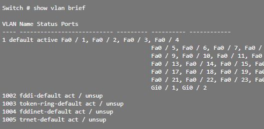
The show vlan command   displays information about the Cisco IOS VLAN subinterfaces. The result shows the two VLAN subinterfaces, GigabitEthernet0 / 0.10 and GigabitEthernet0 / 0.30.

R1 # show vlan

Virtual LAN ID: 10 (IEEE 802.1Q Encapsulation)

vLAN Trunk Interface: GigabitEthernet0 / 0.10

Protocols Configured: Address: Received: Transmitted:
 IP 172.17.10.1 11 18

Virtual LAN ID: 30 (IEEE 802.1Q Encapsulation)

vLAN Trunk Interface: GigabitEthernet0 / 0.30

Protocols Configured: Address: Received: Transmitted:
 IP 172.17.30.1 11 8
Examine the routing table using the command show ip route . In the example, the routes defined in the routing table indicate that they are associated with specific subinterfaces, rather than separate physical interfaces. There are two routes in the routing table: one route goes to subnet 172.17.10.0, which is connected to the local subinterface G0 / 0.10; the other route goes to subnet 172.17.30.0, which is connected to the local subinterface G0 / 0.30. The router uses the routing table to determine where to send the traffic it receives. For example, if the router receives a packet in subinterface G0 / 0.10 destined for subnet 172.17.30.0, it will identify that it must send the packet through subinterface G0 / 0.30 to reach the hosts in subnet 172.17.30.0.

R1 # show ip route
Codes: L - local, C - connected, S - static, R - RIP, M - mobile, 
 B - BGP
 D - EIGRP, EX - EIGRP external, O - OSPF, 
 IA - OSPF inter area 
 N1 - OSPF NSSA external type 1, 
 N2 - OSPF NSSA external type 2
 E1 - OSPF external type 1, E2 - OSPF external type 2
 i - IS-IS, su - IS-IS summary, L1 - IS-IS level-1, 
 L2 - IS-IS level-2
 ia - IS-IS inter area, * - candidate default, 
 U - per-user static route
 or - ODR, P - periodic downloaded static route, H - NHRP,
 l - LISP
 + - replicated route,% - next hop override

Gateway of last resort is not set

172.17.0.0/16 is variably subnetted, 4 subnets, 2 masks
C 172.17.10.0/24 is directly connected, GigabitEthernet0 / 0.10
L 172.17.10.1/32 is directly connected, GigabitEthernet0 / 0.10
C 172.17.30.0/24 is directly connected, GigabitEthernet0 / 0.30
L 172.17.30.1/32 is directly connected, GigabitEthernet0 / 0.30

ROUTING VERIFICATION

After configuring the router and switch to perform VLAN routing, the next step is to verify host-to-host connectivity. Access to devices in remote VLANs can be tested with the command ping.
PING TEST
The ping Send an ICMP echo request to the destination address. When a host receives an ICMP echo request, it responds with an ICMP echo response to confirm that it received that request. The ping calculates the elapsed time, for which it uses the time difference between the moment the echo request was sent and the moment the echo response was received. The elapsed time is used to determine the latency of the connection. Upon receiving a successful response, confirm that there is a route between the sending device and the receiving device.

PC1> ping 172.17.30.23
Pinging 172.17.30.23 with 32 bytes of data:
Reply from 172.17.30.23: bytes = 32 time = 17ms TTL = 127>
Reply from 172.17.30.23: bytes = 32 time = 15ms TTL = 127>
Reply from 172.17.30.23: bytes = 32 time = 18ms TTL = 127>
Reply from 172.17.30.23: bytes = 32 time = 19ms TTL = 127>

Ping statistics for 172.17.30.23:>
Packets: Sent = 4, Received = 4, Lost = 0 (0% loss),
Approximate round trip times in milli-seconds:
Minimum = 15ms, Maximum = 19ms, Average = 17ms
TRACERT TEST
Tracert is a practical utility used to confirm the routed route taken between two devices. On UNIX systems, the utility is specified as traceroute . Tracert also uses the ICMP to determine the route taken, but uses the ICMP echo requests with specific lifetime values ​​defined in the frame.

PC1> tracert 172.17.30.23
Tracing route to 172.17.30.23 over a maximum of 30 hops:
 9 ms 7 ms 9 ms 172.17.10.1
 16 ms 15 ms 16 ms 172.17.30.23
Trace complete.
The lifetime value accurately determines the amount of router hops that the ICMP echo can reach. The first ICMP echo request is sent with a lifetime value configured to expire on the first router on the route to the destination device.
When the ICMP echo request on the first route is exceeded, an ICMP message is forwarded from the router to the source device. The device registers the response from the router and proceeds to send another echo request from the ICMP, but this time with a longer lifetime value. This allows the ICMP echo request to traverse the first router and reach the second device on the route to the final destination. The process is repeated recursively until, finally, the ICMP echo request is sent to the final destination device. After the command is issued tracert After running, a list of the router's input interfaces reached by the ICMP echo request on its way to the destination is displayed.
In the example, the utility ping could send an ICMP echo request to the IP address of PC3. In addition, the utility tracert confirms that the path to PC3 is through the IP address of subinterface 172.17.10.1 of router R1.

Monday, 14 October 2019

How to Configure Vlan On Cisco Router | VLAN trunks Troubleshooting

How to Configure Vlan On Cisco Router

This section describes How to Configure Vlan On Cisco Router and VLAN trunks. In post is specifically related to configuration of VLAN, if you want to learn about what is the VLAN you can visit the previous post. 
Table of Contents
  1. VLAN ranges on Catalyst switches
  2. Creation of a VLAN
  3. Assignment of ports to VLAN networks
  4. How to Delete a VLan
  5. Verification of VLAN information
  6. VLAN Trunks Configuration
  7. VLAN Troubleshooting
  8. Troubleshooting trunks configurations


How many VLANs you can configure on Cisco Switch


Different Cisco Catalyst switches support various amounts of VLAN. The amount of VLANs they support is sufficient to meet the needs of most organizations. For example, the Catalyst 2960 and 3560 series switches support more than 4000 VLANs. The normal range VLANs on these switches are numbered from 1 to 1005, and the extended range VLANs are numbered from 1006 to 4094. The following illustration shows the available VLANs on a Catalyst 2960 switch running Cisco IOS, version 15.x.


Normal Range VLAN

·         It is used in networks of small and medium businesses and companies.
·         It is identified by a VLAN ID between 1 and 1005.
·         IDs from 1002 to 1005 are reserved for Token Ring VLANs and fiber optic distributed data interface (FDDI).
·         IDs 1 and 1002 to 1005 are created automatically and cannot be deleted.
·         The settings are stored in a VLAN database file, called vlan.dat. The vlan.dat file is located in the flash memory of the switch.
·         The VLAN trunk link protocol (VTP), which allows you to manage VLAN settings between switches, can only discover and store VLAN networks of normal range.

Extended VLAN Range

·         It enables service providers to expand their infrastructure to a larger number of customers. Some global companies may be large enough to need the IDs of extended range VLANs.
·         They are identified by a VLAN ID between 1006 and 4094.
·         The settings are not written to the vlan.dat file.
·         They support fewer VLAN features than normal range VLANs.
·         They are saved, by default, in the running configuration file.
·         VTP does not learn extended range VLANs.

How to create VLAN on Cisco Switch

When configuring VLAN networks of normal range, the configuration details are stored in the flash memory of the switch in a file called vlan.dat. The flash memory is persistent and does not require the copy running-config startup-config command. However, because other details are usually configured on Cisco switches at the same time that VLANs are created, it is advisable to save the changes to the running configuration in the startup configuration. The following table shows the syntax of the Cisco IOS command that is used to add a VLAN to a switch and assign it a name. It is recommended to name each VLAN in the configuration of a switch.
Description
Command
Enter global configuration mode.
S1 # configure terminal
Create a VLAN with a valid ID number.
S1 (config) #vlan id-vlan
Specify a unique name to identify the VLAN.
S1 (config-vlan) #name vlan-name
Return to privileged EXEC mode.
S1 (config-vlan) # end
Table of Commands for Creating a VLAN.

VLAN Configuration Example

In following figure, it is shown how VLAN is configured for students (VLAN 20) on switch S1. In the topology example, the student's computer (PC2) has not yet been associated with any VLAN, but has the IP address 172.17.20.22.
S1# configure terminal
S1(config)# vlan 20
S1(config-vlan)# name student
S1(config-vlan)# end
The switchport access vlan command   forces the creation of a VLAN if it does not already exist on the switch. For example, VLAN 30 is not present in the result of the show vlan brief command   of the switch. If the switchport access vlan 30 command is entered   on any interface without prior configuration, the switch displays the following:
% Access VLAN does not exist. Creating vlan 30
How change the membership of Port of VLAN
There are several ways to change the membership of ports in a VLAN. The following table shows the syntax for changing the membership of a switch port of VLAN 1 with the  no switchport access vlan command of the interface configuration mode.
Description
Command
Enter global configuration mode.
S1 # configure terminal
Remove the VLAN assignment from the port.
S1 (config-if) # no switchport access vlan
Return to privileged EXEC mode.
S1 (config-if) # end
VLAN Assignment Elimination Table.

CONFIGURATION EXAMPLE

The F0 / 18 interface was previously assigned to VLAN 20. The no switchport access vlan command for the F0 / 18 interface is entered. Examine the result of the show vlan brief command   that follows immediately, as shown in the previous result. The show vlan brief command   shows the type of VLAN assignment and membership for all switch ports. The show vlan brief command   shows a line for each VLAN. The result for each VLAN includes the name, status and switch ports of the VLAN.

VERIFICATION EXAMPLE

VLAN 20 is still active, even if it has no ports assigned. The following scheme shows that the result of the show interfaces f0 / 18 switchport command   verifies that the access VLAN for interface F0 / 18 has been reset to VLAN 1.

ASSIGNING A PORT TO A VLAN

The VLAN membership of a port can be easily changed. It is not necessary to first remove a port from a VLAN to change its VLAN membership. When the VLAN membership of an access port is reassigned to another existing VLAN, the new VLAN membership simply replaces the previous VLAN membership. Next, port F0 / 11 was assigned to VLAN 20.

S1 # config t
S1 (config) # interface F0 / 11
S1 (config-if) # switchport mode access
S1 (config-if) # switchport access vlan 20
S1 (config-if) # end

How to delete a VLAN

In the illustration, the global configuration mode command no vlan  id-vlan  is used to remove VLAN 20 from the switch. Switch S1 had a minimal configuration with all ports in VLAN 1 and an unused VLAN 20 in the VLAN database. The show vlan brief command   verifies that VLAN 20 is no longer present in the vlan.dat file after using the no vlan 20 command.
S1 # conf t
S1 (config) # no vlan 20
S1 (config) # end
Caution: Before deleting a VLAN, reassign all member ports to a different VLAN. Ports that do not transfer to an active VLAN cannot communicate with other hosts once the VLAN is removed and until they are assigned to an active VLAN.
Alternatively, the entire vlan.dat file can be deleted with the delete flash command: vlan.dat in the privileged EXEC mode. The abbreviated version of the command (delete vlan.dat) can be used if the vlan.dat file was not moved from its default location. After issuing this command and reloading the switch, the previously configured VLANs are no longer present. This returns the switch to the factory default condition with respect to the VLAN configuration.

VERIFICATION OF VLAN INFORMATION

Once a VLAN is configured, the configuration can be validated with the Cisco IOS show commands.
show vlan [ brief | id  id-vlan | name  vlan-name | summary ]
The following table shows the options for the show vlan  and  show interfaces commands  .


Description
Command
Show a line for each VLAN with its name, status and ports.
brief
Show information about a single VLAN identified by its ID number.
For the vlan-id, the range is 1 to 4094.
id id-vlan
Show information about a single VLAN identified by name. The name of the VLAN is an ASCII string of 1 to 32 characters.
name vlan-name
Show the summary of VLAN information.
summary
Show vlan command table

USE THE SHOW VLAN COMMAND

In the following example, the show vlan name student command   produces a result that is not easily interpreted. The show vlan summary command   shows the count of all configured VLANs. The result shows seven VLANs.

USE THE SHOW INTERFACES VLAN COMMAND

The show interfaces vlan  id-vlan  command  shows details that exceed the scope of this course. The important information appears on the second line of the following scheme, which indicates that VLAN 20 is active.

VLAN TRUNKS CONFIGURATION

A VLAN trunk link is a layer 2 link of the OSI model between two switches that carries traffic for all VLANs (unless the list of allowed VLANs is restricted manually or dynamically). To enable trunk links, configure the ports at either end of the physical link with parallel command sets. To configure a switch port at one end of a trunk link, use the switchport mode trunk command. With this command, the interface switches to permanent trunk mode. The port establishes a dynamic trunk link protocol (DTP) negotiation to convert the link into a trunk link, even if the interface connected to it does not accept the change. In this course, the switchport mode trunk command   is the only method that is implemented for trunking configuration.
The following table shows the syntax of the Cisco IOS command to specify a native VLAN (other than VLAN 1). In the example, VLAN 99 is configured as a native VLAN with the switchport trunk native vlan 99 command.
Description
Command
Enter global configuration mode.
S1 # configure terminal
Enter the interface configuration mode.
S1 (config) # interface interface_id
Make the link a trunk link.
S1 (config-if) # switchport mode trunk
Specify a native VLAN for frames without labels.
S1 (config-if) # switchport trunk native vlan id_vlan
Specify the list of VLANs that will be allowed on the trunk link.
S1 (config-if) # switchport trunk allowed vlan vlan-list
Return to privileged EXEC mode.
S1 (config-if) # end
Trunk Link Configuration Table
Use the switchport trunk allowed vlan   Cisco IOS list-vlan command  to specify the list of VLANs that will be allowed on the trunk link.
VLAN TOPOLOGY EXAMPLE

In following image, VLANs 10, 20 and 30 support the Teaching, Student and Guest computers (PC1, PC2 and PC3). Port F0 / 1 of switch S1 was configured as a trunk link port and forwards traffic for VLANs 10, 20 and 30. VLAN 99 was configured as a native VLAN.

VLAN 10 - Faculty / Staff - 172.17.10.0/24
VLAN 20 - Students - 172.17.20.0/24
VLAN 30 - Guest - 172.17.30.0/24
VLAN 99 - Native - 172.17.99.0/24
The following shows the configuration of port F0 / 1 of switch S1 as a trunk link port. The native VLAN is changed to VLAN 99 and the list of allowed VLANs is restricted to 10, 20, 30 and 99.
S1 (config) # interface FastEthernet0 / 1
S1 (config-if) # switchport mode trunk
S1 (config-if) # switchport trunk native vlan 99
S1 (config-if) # switchport trunk allowed vlan 10,20,30,99
S1 (config-if) # end

RESET THE TRUNK LINK TO THE DEFAULT STATE

The following table shows the commands to remove the allowed VLANs and restore the native VLAN from the trunk. When it is restored to the default state, the trunk link allows all VLANs and uses VLAN 1 as a native VLAN.
Description
Command
Enter global configuration mode.
S1 # configure terminal
Enter the interface configuration mode.
S1 (config) # interface interface_id
Establish the trunk link to allow all VLANs.
S1 (config-if) # no switchport trunk allowed vlan
Reset the native VLAN to the default value.
S1 (config-if) # no switchport trunk native vlan
Return to privileged EXEC mode.
S1 (config-if) # end
Reset table of values ​​configured in trunks
The commands used to reset all trunk link features of a trunk interface to the default settings are now displayed. The show interfaces f0 / 1 switchport command reveals that the trunk link was reconfigured in a default state.
Finally, the example result shows the commands used to remove the trunk link feature of port F0 / 1 of switch S1. The show interfaces f0 / 1 switchport command reveals that the F0 / 1 interface is now in static access mode.

TRUNK LINK CONFIGURATION VERIFICATION


The following result shows the configuration of port F0 / 1 of switch S1. The configuration is verified with the command show interfaces id-switchport interface.
In the highlighted upper area, it is shown that the administrative mode of port F0 / 1 was set to trunk. The port is in trunk mode. In the next highlighted area, it is verified that the native VLAN is VLAN 99. Further down in the result, in the highlighted lower area, it is shown that all VLANs are enabled on the trunk link.

VLAN TROUBLESHOOTING

Each VLAN must correspond to a single IP subnet . If two devices on the same VLAN have different subnet addresses, they cannot communicate. This is a frequent problem and is easily solved by identifying the incorrect configuration and changing the subnet address to a correct address.
In above image, PC1 cannot connect to the Web / TFTP server shown.
The verification of the IPv4 configuration options of PC1, which is shown in the following result, reveals the most frequent error in the configuration of VLAN networks: a badly configured IPv4 address. PC1 was configured with IPv4 address 172.172.10.21, but should have been configured with address 172.17.10.21.

PC1> ipconfig

IP Address ...................: 172.172.10.21
Subnet Mask ..................: 255.255.0.0
Default Gateway ..............: 0.0.0.0

The PC1 Fast Ethernet configuration dialog box shows the updated IPv4 address, 172.17.10.21. The result shown at the bottom indicates that PC1 regained connectivity to the Web / TFTP server located at IPv4 address 172.17.10.30.

PC1> ping 172.17.10.30
Pinging 172.17.10.30 with 32 bytes of data:
Reply from 172.17.10.30: Bytes = 32 Time = 147ms TTL = 128

How to Troubleshoot MISSING VLANS

If there is still no connection between the devices in a VLAN but the IP addressing problems have been ruled out.

Step 1 : Use the show vlan command   to verify if the port belongs to the expected VLAN. If the port was assigned to an incorrect VLAN, use the switchport access vlan command   to correct VLAN membership. Use the show mac address-table command   to review which addresses were obtained on a particular port on the switch and to which VLAN that port was assigned, as shown below:
Step 2 : If the VLAN to which the port was assigned is removed, the port becomes inactive. The ports of a deleted VLAN will not be indicated in the result of the show vlan command  . Use the show interfaces switchport command   to verify that the inactive VLAN is assigned to the port, as shown:
In the previous result, the MAC addresses that were obtained in the F0 / 1 interface are shown. It can be seen that the MAC address 000c.296a.a21c was obtained at interface F0 / 1 of VLAN 10. If this is not the expected VLAN number, change the VLAN port membership with the switchport access vlan command. Each port of a switch belongs to a VLAN. If the VLAN to which the port belongs is deleted, it becomes inactive. None of the ports belonging to the VLAN that was deleted can communicate with the rest of the network. Use the show interface f0 / 1 switchport command   to verify if the port is inactive. If the port is inactive, it does not work until the VLAN is created with the global configuration command vlan  id-vlan  or the VLAN is removed from the port with the no switchport access vlan  id-vlan command  .

TROUBLESHOOTING TRUNKS

One of the common tasks of network administrators is to solve problems of trunk or port link formation that behaves incorrectly as trunk ports. Occasionally, a switch port may behave as a trunk link port, even if it was not configured as such. For example, an access port can accept frames from VLAN networks other than the VLAN to which it was assigned. This is known as "VLAN filtration."
TROUBLESHOOTING COMMANDS
To solve problems of trunk links that are not formed or VLAN filtering, proceed as follows:
·         Step 1 : Use the show interfaces trunk command   to verify if there is a match between the local native VLAN and the peers. If the native VLAN does not match at both ends, there is a VLAN leak.
·         Step 2 : Use the show interfaces trunk command   to verify if a trunk link was established between the switches. Staticly configure trunks whenever possible. Cisco Catalyst switch ports use DTP by default and attempt to negotiate a trunk.
To show the status of the trunk link and the native VLAN used in it, and verify the establishment of that link, use the show interfaces trunk command  . Next, it is shown that the native VLAN at one end of the trunk link was changed to VLAN 2. If one end of the trunk link is configured as native VLAN 99 and the other end as native VLAN 2, the frames that are sent from the trunk VLAN 99 on one end are received on VLAN 2 on the other end. VLAN 99 is filtered in segment VLAN 2.
SW1 # show interfaces f0 / 1 trunk

Port Mode Encapsulation Status Native vlan
Fa0 / 1 car 802.1q         trunking 2
CDP displays a native VLAN incompatibility warning on a trunk link with this message:
* Mar 1 06: 45: 26.232:% CDP-4-NATIVE_VLAN_MISMATCH: Native VLAN mismatch discovered on FastEthernet0 / 1 (2), with S2 FastEthernet0 / 1 (99).
If there is a native VLAN incompatibility, connectivity problems occur on the network. Data traffic for VLANs other than the two native VLANs configured is correctly propagated through the trunk link, but data related to any of the native VLANs is not propagated correctly through the trunk link.

As shown above, the incompatibility problems of the native VLAN do not prevent the trunk link from forming. To resolve a native VLAN incompatibility, configure the native VLAN to be the same VLAN on both sides of the link.

COMMON ISSUES WITH TRUNKS

In general, trunk link problems are due to incorrect configuration. When configuring VLANs and trunks in a switched infrastructure, the most frequent configuration errors are as follows:
·         Incompatibility of native VLAN:  Trunk link ports were configured with different native VLANs. This configuration error generates console notifications and can cause routing problems between VLANs, among other inconveniences. This represents a security risk.
For example, one port is defined as VLAN 99 and the other as VLAN 100.
·         Incompatibilities of trunk mode:  A trunk port is configured in a mode that is not compatible for trunk links on the corresponding peer port. These configuration errors cause the trunk link to stop working. Ensure that both sides of the trunk link are configured with the switchport mode trunk command  . The other trunk link configuration commands exceed the scope of this course.
For example, one side of the trunk link is configured as an access port.

VLANs allowed on trunk links:  The list of VLANs allowed on a trunk link with the current VLAN trunk requirements was not updated. In this case, unexpected traffic or no traffic is sent to the trunk link.
The list of allowed VLANs does not support the current VLAN trunk requirements.
If a problem with a trunk link is detected and the cause is unknown, start troubleshooting with a review of the trunk links to determine if there is a native VLAN incompatibility. If that is not the cause, check if there is a trunk link mode incompatibility and, finally, check the list of VLANs allowed on the trunk link. On the next two pages, we discuss how to troubleshoot frequent trunk links.

WRONG PORT MODE

Typically, trunk links are statically configured with the switchport mode trunk command  . The trunk link ports of Cisco Catalyst switches use DTP to negotiate link status. When a port on a trunk link is configured with a trunk link mode that is not compatible with the neighboring trunk link port, a trunk link cannot be formed between the two switches.

INCORRECT VLAN LIST

For a VLAN traffic to be transmitted through a trunk link, it must be allowed on that link. To do this, use the switchport trunk allowed vlan  command id-vlan  .