Showing posts with label NAT. Show all posts

Monday, 21 October 2019

Configuring NAT with IPv6 on Cisco Router

Configuring NAT with IPv6 on Cisco Router

This is a special article in which you learn how to Configuring NAT with IPv6 on Cisco Router. The issue of IPv4 address space depletion has been a priority for the IETF since the early 1990s. The combination of private IPv4 addresses defined in RFC 1918 and NAT plays a decisive role in delaying this exhaustion. NAT has considerable disadvantages, and in January 2011, IANA assigned its latest IPv4 addresses to RIRs.
One of the benefits of NAT for IPv4 that were not intentional is that it hides the private public Internet network. NAT has the advantage that it offers a considerable level of security by denying access to internal hosts to computers on the Internet. However, it should not be considered as a substitute for adequate network security, such as that provided by a firewall.

Is NAT possible with IPV6?

In RFC 5902, the Internet Architecture Council (IAB) included the following quote on the translation of IPv6 network addresses:

“In general, it is believed that a NAT box provides a level of protection because external hosts cannot directly initiate a communication with the hosts behind a NAT. However, NAT boxes should not be confused with firewalls. As discussed in section 2.2 of RFC4864, the act of translation itself does not provide security. The state filtering function can provide the same level of protection without requiring a translation function. ”

With a 128-bit address , IPv6 provides 340 sextillion addresses . Therefore, address space is not a problem. IPv6 was developed with the intention that NAT for IPv4 with its translation between public and private IPv4 addresses is unnecessary. However, IPv6 implements a form of NAT. IPv6 includes its own private IPv6 and NAT address space, which are implemented differently from what is done for IPv4.

UNIQUE LOCAL IPV6 ADDRESSES

Unique local IPv6 addresses (ULAs) resemble private IPv4 addresses defined in RFC 1918, but there are also considerable differences. The purpose of ULAs is to provide IPv6 address space for communications within a local site, they are not intended to provide additional IPv6 address space or a security level.

As shown in the illustration, ULAs have the prefix FC00 :: / 7, which produces a range of first hextete ranging from FC00 to FDFF. The next bit is set to 1 if the prefix is ​​assigned locally. It is possible that in the future it can be set to 0. The next 40 bits correspond to a global ID followed by a 16-bit subnet ID. These first 64 bits are combined to create the ULA prefix. This allows the remaining 64 bits to be used for the interface ID or, in terms of IPv4, the host portion of the address.

ULA FEATURES

Unique local addresses are defined in RFC 4193. ULAs are also known as "local IPv6 addresses" (not to be confused with link-local IPv6 addresses) and have several features, including the following:

  • They allow sites to be combined or interconnected privately, without generating conflicts between addresses and without re-numbering the interfaces that use these prefixes.
  • They are independent of any ISP and can be used for communications within a site without having Internet connectivity.
  • They cannot be routed over the Internet; however, if they are filtered by routing or DNS, there is no conflict with other addresses.

ULAs are not as simple as the addresses defined in RFC 1918. Unlike private IPv4 addresses, the IETF did not intend to use a NAT form to translate between unique local addresses and global unicast IPv6 addresses.

IPV6 AND NAT

NAT for IPv6 is used in a very different context than NAT for IPv4. NAT varieties for IPv6 are used to provide transparent access between IPv6 only networks and IPv4 only networks. It is not used as a form of translation from private IPv6 to global IPv6.
Ideally, IPv6 be run natively whenever possible. That is, on IPv6 devices that communicate with each other through IPv6 networks. However, to assist in the change from IPv4 to IPv6, the IETF developed several transition techniques that support a variety of situations from IPv4 to IPv6, such as dual-stack, tunneling and translation.

Dual-stack is when the devices execute protocols associated with IPv4 and IPv6. Tunneling for IPv6 is the process of encapsulating an IPv6 package within an IPv4 package. This allows the IPv6 packet to be transmitted through an IPv4-only network.
NAT for IPv6 should not be used as a long-term strategy, but as a temporary mechanism to contribute to the migration from IPv4 to IPv6. Over the years, there were several types of NAT for IPv6, including network address translation / protocol translation (NAT-PT).

Configure Cisco Port Forwarding with Cisco IOS Router

Configure Cisco Port Forwarding with Cisco IOS Router

In this article you will understand what is port forwarding and how to Configure Cisco Port Forwarding with Cisco router.
Port forwarding is used to forward traffic directed to a specific network port from one network node to another. This technique allows an external user to reach a port on a private IPv4 address (within a LAN) from outside through a router with NAT enabled.
In general, peer-to-peer operations and programs for file sharing, such as outgoing web server applications and FTP, require router ports to be forwarded or opened to allow these applications to function, as shown in Image 1. Because NAT hides internal addresses, peer-to-peer communication only works from the inside out where NAT can assign outgoing requests to incoming responses.

The problem is that NAT does not allow requests initiated from abroad. This situation can be resolved manually. Port forwarding can be configured to identify specific ports that can be forwarded to internal hosts.

What is Port Forwarding ?

Remember that Internet software applications interact with the user ports that need to be open or available for those applications. Different applications use different ports. This makes applications and routers identify network services predictably. For example, HTTP works through the well-known port 80. When someone enters the address  http://cisco.com , the browser displays the Cisco Systems, Inc. website. Note that it is not necessary to specify the port number HTTP for the page request, since the application assumes that it is port 80.
In Image 2, the owner of a small business that uses a point of sale (PoS) server is shown to track sales and inventories in the store. The server can be accessed from the store but, because it has a private IPv4 address, it is not possible to access it publicly from the Internet. Enabling the local router for port forwarding would allow the owner to access the point of sale server anywhere from the Internet. Port forwarding on the router is configured with the destination port number and the private IPv4 address of the point of sale server. To access the server, the client software would use the public IPv4 address of the router and the destination port of the server.

EXAMPLE OF WIRELESS ROUTER

Image 3 shows the configuration window of the simple assigned port forwarding corresponding to a Packet Tracer wireless router. By default, port forwarding is not enabled on the router.

If you specify the internal local address to which requests should be forwarded, it is possible to enable port forwarding for applications. In the figure, requests for HTTP services that come from the wireless router are forwarded to the web server with the following internal local address: 192.168.1.254. If the IPv4 address of the external WAN of the wireless router is 209.165.200.225, the user can enter  http://www.example.com  and the wireless router will redirect the HTTP request to the internal web server of the IPv4 address 192.168.1.254, by middle of the default port number: 80.
A port other than the default port 80 can be specified. However, the external user would have to know the specific port number to use. To specify a different port, the value of the External Port field is modified in the Single Port Forwarding window.

Configure Port Forwarding with Cisco iOS

The Cisco IOS commands used to implement port forwarding are similar to those used to configure static NAT . Basically, port forwarding is a static NAT translation with a specific TCP or UDP port number.

The static NAT command that is used to configure port forwarding with IOS is shown below.

ip nat inside source { static { tcp | udp local-ip local-port global-ip global-port} [ extendable ]
Parameter
Description
tcp or udp
Indicates whether this is a TCP or UDP port number.
ip-local
This is the IPv4 address assigned to the host in the internal network, generally, of the private address space defined in RFC 1918.
local port
Set the local TCP / UDP port in a range of 1 to 65,535. This is the port number on which the server listens.
global ip
This is the globally unique IPv4 address of an internal host. This is the IP address used by external clients to reach the internal server.
global port
Set the global TCP / UDP port in the range of 1 to 65,535. This is the port number used by external clients to reach the internal server.
extendable
The extendable option is applied automatically. The extendable keyword allows the user to configure several ambiguous static translations; that is, translations with the same local or global address. It allows the router to extend the translation to more than one port, if necessary.
Command table for port forwarding with IOS.

Port Forwarding CONFIGURATION EXAMPLE

In following figure, an example of port forwarding configuration with IOS commands on router R2 is shown.

Sets the static translation between an internal local address and a local port, and between an internal global address and a global port:
R2 (config) # ip nat inside source static 
tcp 192.168.10.254 80 209.165.200.225 8080
Identify the 0/0/0 serial interface as an internal NAT interface:
R2 (config) # interface Serial0 / 0/0
R2 (config-if) # ip nat inside
Identify the serial interface 0/1/0 as an external NAT interface:
R2 (config) # interface Serial0 / 1/0
R2 (config-if) # ip nat outside
The 192.168.10.254 address is the internal local IPv4 address of the web server listening on port 80. Users will access this internal web server with the global IPv4 address 209.165.200.225, a unique public IPv4 address globally. In this case, it is the address of the Serial interface 0/1/0 of R2. The global port is configured as 8080. This is the destination port that is used together with the global IPv4 address 209.165.200.225 to access the internal web server. Observe the following command parameters within the NAT configuration:

  • ip-local = 192.168.10.254
  • local port = 80
  • ip-global = 209.165.200.225
  • global port = 8080

When a well-known port number is not used, the client must specify the application's port number.
Like other types of NAT, port forwarding requires that internal and external NAT interfaces be configured.

VERIFICATION OF PORT FORWARDING

As in the case of static NAT, the show ip nat translations command can be used to verify port forwarding:

R2 # show ip nat translations
Pro Inside global Inside local Outside local Outside global
tcp 209.165.200.225:8080 192.168.10.254:80 209.165.200.254:46088 209.165.200.254:46088
tcp 209.165.200.225:8080 192.168.10.254:80 --- ---
R2 #
In the example, when the router receives the packet with the internal global IPv4 address 209.165.200.225 and a destination TCP port 8080, the router performs a search in the NAT table with the destination IPv4 address and the destination port as keys . Next, the router translates the address to the internal local address of host 192.168.10.254 and destination port 80. Then, the R2 forwards the packet to the web server. In the case of return packages from the web server to the client, this process is reversed.

PAT Configuration on Cisco NAT overload

PAT Configuration on Cisco NAT overload

This section covers PAT Configuration on Cisco NAT overload or NAT overload. You will find the complete commands along with a practical example. PAT is the types of NAT, static NAT & Dynamic NAT are the other examples.
PAT (also called “NAT with overload”) preserves the addresses of the set of internal global addresses by allowing the router to use an internal global address for many internal local addresses. In other words, a single public IPv4 address can be used for hundreds, even thousands of internal private IPv4 addresses. When this type of translation is configured, the router maintains enough information about the higher-level protocols, TCP or UDP port numbers, for example, to translate the internal global address back to the correct internal local address. When multiple internal local addresses are assigned to an internal global address, the TCP or UDP port numbers of each internal host distinguish between local addresses.

Steps to configure PAT on Cisco Router

There are two ways to configure PAT, depending on how the ISP assigns public IPv4 addresses. First, the ISP assigns more than one public IPv4 address to the organization and, secondly, it assigns a single public IPv4 address that is required for the organization to connect to the ISP. s
If more than one public IPv4 address was issued for a site, these addresses may be part of a set used by PAT. This is similar to dynamic NAT, with the exception that there are not enough public addresses to make a one-to-one assignment between internal and external addresses. A large number of devices share the small set of addresses.
The following table shows the steps to configure PAT to use an address set. The main difference between this configuration and the one-to-one dynamic NAT configuration is that the keyword overload is used  . The overload  keyword  enables PAT.
Steps
Command
1. Define the set of global addresses that should be used for overload translation.
ip nat pool first-ip-ip last name { netmask netmask | prefix-length prefix-length }
2. Define a standard access list that allows the addresses to be translated.
access-list access-list- number allow source [wildcard-origin]
3. Specify the access list and set defined in the previous steps to establish the overload translation.
ip nat inside source list access-list-number pool name overload
4. Identify the internal interface.
interface type ip number
nat inside
5. Identify the external interface.
interface type ip number
nat outside
Table of steps to configure PAT.

PAT configuration example 

The sample configuration shown in Image 1 sets the overhead translation for the NAT set called NAT-POOL2. NAT-POOL2 contains the addresses from 209.165.200.226 to 209.165.200.240. Hosts on the 192.168.0.0/16 network are subject to translation. The S0 / 0/0 interface is identified as an internal interface, and the S0 / 1/0 interface is identified as an external interface.
R2 (config) # ip nat pool NAT-POOL2 209.165.200.226 209.165.200.240 
netmask 255.255.255.224
R2 (config) # access-list 1 permit 192.168.0.0 0.0.255.255
R2 (config) # ip nat inside source list 1 pool NAT-POOL2 overload
R2 (config) # interface Serial0 / 0/0
R2 (config-if) # ip nat inside
R2 (config) # interface Serial0 / 1/0
R2 (config-if) # ip nat outsid

Steps to Configure PAT

In Image 2, the topology of a PAT implementation for the translation of a single public IPv4 address is shown. In the example, all hosts on the 192.168.0.0/16 network (which matches ACL 1) that send traffic to the Internet through router R2 are translated to IPv4 address 209.165.200.225 (IPv4 address of interface S0 / 1/0). Traffic flows are identified by the port numbers in the NAT table, since the keyword overload was used  .

The following table shows the steps that must be followed to configure PAT with a single IPv4 address. If there is only a single public IPv4 address available, the overhead configuration generally assigns the public address to the external interface that connects to the ISP. All internal addresses are translated to the only IPv4 address when they leave the external interface.
Steps
Command
1. Define a standard access list that allows the addresses to be translated.
access-list access-list- number permit origin [wildcard-origin]
2. Specify the ACL, output interface and overload options to establish the dynamic source translation.
ip nat inside source list access-list- number interface type number overload
3. Identify the internal interface.
interface type ip number
nat inside
4. Identify the external interface.
interface type ip number
nat outside
Table of steps to configure PAT: Unique address.

The configuration is similar to that of dynamic NAT , except that, instead of a set of addresses, the keyword interface is used   to identify the external IPv4 address. Therefore, no NAT set is defined.

PAT PROCESS

The NAT process with overload is the same, whether a set of addresses or a single address is used. In the previous example of PAT, PC1 wishes to communicate with the web server Svr1 through a single public IPv4 address. At the same time, another client, PC2, wants to establish a similar session with the Svr2 web server. Both PC1 and PC2 were configured with private IPv4 addresses, with R2 enabled for PAT.

COMPUTER TO SERVER PROCESS


  • 1 . In Image 3, it is shown that PC1 and PC2 send packets to servers Svr1 and Svr2, respectively. PC1 has the source IPv4 address 192.168.10.10 and uses TCP source port 1444. PC2 has the source IPv4 address 192.168.10.11 and, by chance, is assigned the same source port 1444.
  • 2 . The package of PC1 arrives first at R2. By using PAT, R2 modifies the source IPv4 address to 209.165.200.225 (internal global address). In the NAT table, there is no other device that uses port 1444, so PAT maintains the same port number. The package is then forwarded to Svr1 on 209.165.201.1.
  • 3 . Next, the PC2 package arrives at R2. PAT is configured to use a single internal global IPv4 address for all translations, 209.165.200.225. As with the translation process for PC1, PAT changes the source IPv4 address of PC2 to the internal global address 209.165.200.225. However, PC2 has the same source port number as a current PAT entry, the translation for PC1. PAT increases the source port number until it is a unique value in its table. In this case, the source port entry in the NAT table and the PC2 packet receive the number 1445.

While PC1 and PC2 use the same translated address, internal global address 209.165.200.225, and the same source port number 1444, the modified port number for PC2 (1445) makes each entry in the table of NAT is unique. This becomes evident when packets are returned from the servers to the clients.

SERVER TO COMPUTER PROCESS


  • 4 . As shown in Image 4, in a typical exchange between client and server, servers Svr1 and Svr2 respond to requests received from PC1 and PC2, respectively. The servers use the source port of the received packet as the destination port and the source address as the destination address for return traffic. Apparently, the servers communicate with the same host on 209.165.200.225, but it is not.
  • 5 . As packets arrive, R2 locates a single entry in its NAT table using the destination address and destination port of each packet. In the case of the Svr1 package, the destination IPv4 address 209.165.200.225 has several entries, but only one with the destination port 1444. By entering its table, R2 changes the destination IPv4 address of the packet to 192.168. 10.10, without the need to modify the destination port. Then, the packet is forwarded to PC1.
  • 6. When the Svr2 package arrives, R2 performs a similar translation. Destination IPv4 address 209.165.200.225 reappears in several entries. However, with destination port 1445, R2 can identify a single translation entry. The destination IPv4 address is modified to 192.168.10.11. In this case, the destination port must also be re-modified to its original value of 1444, which is stored in the NAT table. Then, the packet is forwarded to PC2.

VERIFICATION OF A PAT

Router R2 was configured to provide PAT to 192.168.0.0/16 clients. When internal hosts leave the R2 router to the Internet, they are translated to an IPv4 address of the PAT set with a single source port number.
To verify PAT, the same commands that are used to verify static and dynamic NAT are used, as shown below. The show ip nat translations  command  shows the translations of two different hosts to different web servers. Note that the same IPv4 address 209.165.200.226 (internal global address) is assigned to two different internal hosts. The source port numbers in the NAT table distinguish the two transactions.

R2 # show ip nat translations
Pro Inside global Inside local Outside local Outside global
tcp 209.165.200.226:51839 192.168.10.10:51839 209.165.201.1:80 209.165.201.1:80
tcp 209.165.200.226:42558 192.168.11.10:42558 209.165.202.129:80 209.165.202.129:80
R2 #
As shown below, the show ip nat statistics command   verifies that NAT-POOL2 has assigned a single address for both translations. The result includes information on the quantity and type of active translations, the NAT configuration parameters, the number of addresses in the set and the amount that was assigned.
R2 # clear ip nat statistics

R2 # show ip nat statistics
Total active translations: 2 (0 static, 2 dynamic; 2 extended )
Peak translations: 2, occurred 00:00:05 ago
Outside interfaces:
 Serial0 / 0/1
Inside interfaces: 
 Serial0 / 1/0
Hits: 4 Misses: 0
CEF Translated packets: 4, CEF Punted packets: 0
Expired translations: 0
Dynamic mappings:
- Inside Source
[Id: 3] access-list 1 pool NAT-POOL2 refcount 2
pool NAT-POOL2 : netmask 255.255.255.224
  start 209.165.200.226 end 209.165.200.240 
 type generic, total addresses 15, allocated 1 (6%), misses 0

Total doors: 0
Appl doors: 0
Normal doors: 0
Queued Packets: 0
R2 #

Dynamic NAT Configuration on Cisco

Dynamic NAT Configuration on Cisco

This is a Complete article on Dynamic NAT Configuration on Cisco with configuration example. You can find all step by step configuration with Cisco commands in details.
While static NAT provides a permanent assignment between an internal local address and an internal global address, dynamic NAT allows automatic assignment of internal local addresses to internal global addresses. Typically, these internal global addresses are public IPv4 addresses. Dynamic NAT uses a group or set of public IPv4 addresses for translation.
Like static NAT, dynamic NAT requires that the internal and external interfaces that participate in NAT be configured. However, while static NAT creates a permanent assignment to a single address, dynamic NAT uses a set of addresses.
Note:  Translation between public and private IPv4 addresses is the most frequent use of NAT. However, NAT translations can be performed between any pair of addresses.
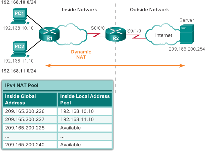
The example topology shown in Image 1 has an internal network that uses addresses from the private address space defined in RFC 1918. There are two LANs connected to router R1: 192.168.10.0/24 and 192.168.11.0/24. Router R2, that is, the border router, was configured for dynamic NAT with a set of public IPv4 addresses from 209.165.200.226 to 209.165.200.240.

The set of public IPv4 addresses (set of internal global addresses) is available for any device in the internal network according to the order of arrival. With dynamic NAT, a single internal address is translated into a single external address. With this type of translation, there must be enough addresses in the set to support all internal devices that need access to the external network at the same time. If all addresses in the set were used, the devices must wait for an address to be available to access the external network.

Steps to configure dynamic NAT on Cisco

The steps and commands used to configure dynamic NAT are shown below.

  • Step 1:  Define the set of addresses that will be used for translation with the ip nat pool command  . Usually, this set is a group of public addresses. The addresses are defined indicating the first and last IPv4 address of the set. The netmask  or  prefix-length keywords   indicate which address bits belong to the network and which ones to the host in the address range.
ip nat pool  name start-ip end-i p { netmask  netmask | prefix-length  prefix-length }
  • Step 2:  Configure a standard ACL to identify (allow) only those addresses that must be translated. An ACL that is too permissive can generate unpredictable results. Remember that at the end of each ACL there is an implicit instruction to  deny everything .
access-list access-list-  number  permit  origin [ wildcard-origin ]
  • Step 3:  Connect the ACL to the assembly. The  ip nat inside source list  access-list-number  pool  name set name is used  to link the ACL to the set. The router uses this configuration to determine which address ( pool ) each device receives ( list ).
ip nat inside source list  access-list-number  pool  name
  • Step 4:  Identify which interfaces are internal with respect to NAT; that is, any interface that connects to the internal network.

interface  type 
ip number nat inside

  • Step 5:  Identify which interfaces are external with respect to NAT; that is, any interface that connects to the external network.

interface  type  
ip number nat outside

Example of dynamic NAT configuration

In Image 2, a topology and an example configuration are shown. This configuration allows translation for all hosts in the 192.168.0.0/16 network, which includes the 192.168.10.0 and 192.168.11.0 LANs, when they generate traffic that enters through S0 / 0/0 and leaves through S0 / 1/0. These hosts are translated to an available address of the set in the range of 209.165.200.226 to 209.165.200.240.

Define a set of public IPv4 addresses with the set name NAT-POOL1.
R2 (config) # <b> ip nat pool NAT-POOL1 209.165.200.226
209.165.200.240 netmask 255.255.255.224
Define the addresses that can be translated.
R2 (config) # access-list 1 permit 192.168.0.0 0.0.255.255
Connect NAT-POOL1 to ACL 1.
R2 (config) # <b> ip nat inside source list 1 pool NAT-POOL1
Identify the 0/0/0 serial interface as an internal NAT interface.
R2 (config) # interface Serial0 / 0/0
R2 (config-if) # ip nat inside
Identify the serial interface 0/1/0 as an external NAT interface.
R2 (config) # interface Serial0 / 1/0
R2 (config-if) # ip nat outside

DYNAMIC NAT PROCESS

With the previous configuration, the illustrations show the dynamic NAT translation process between two clients and the web server:

INSIDE OUT


  • 1 . The hosts with the source IPv4 addresses (PC1 and PC2) send packets to request connection to the server at the public IPv4 address (209.165.200.254).
  • 2 . R2 receives the first host package 192.168.10.10. Because this package was received on an interface configured as an internal NAT interface, R2 verifies the NAT configuration to determine if this package should be translated. As the ACL allows this package, R2 translates it. R2 consults its NAT table. Because there is no translation entry for this IPv4 address, R2 determines that the source address 192.168.10.10 must be translated dynamically. R2 selects an available global address from the dynamic address set and creates a translation entry, 209.165.200.226. The initial source IPv4 address (192.168.10.10) is the internal local address, and the translated address is the internal global address (209.165.200.226) in the NAT table.

For the second host, 192.168.11.10, the R2 repeats the procedure, selects the next available global address from the dynamic address set and creates a second translation entry, 209.165.200.227.

  • 3 . R2 replaces the internal local source address of PC1, 192.168.10.10, with the translated internal global address 209.165.200.226 and resends the packet. The same process is carried out for the PC2 package with the address translated for this computer (209.165.200.227).

FROM THE OUTSIDE IN


  • 4 . The server receives the packet from PC1 and responds with the destination IPv4 address 209.165.200.226. When the server receives the second packet, it responds to PC2 with the destination IPv4 address 209.165.200.227.
  • 5th . When R2 receives the packet with destination IPv4 address 209.165.200.226, it performs a search in the NAT table. With the assignment of the table, R2 translates the address back to the internal local address (192.168.10.10) and forwards the packet to PC1.
  • 5b . When R2 receives the packet with the destination IPv4 address 209.165.200.227, it performs a search in the NAT table. With the assignment of the table, R2 translates the address back to the internal local address (192.168.11.10) and forwards the packet to PC2.
  • 6 . PC1 and PC2 receive the packets and continue the conversation. The router performs steps 2 through 5 for each packet. (Step 6 does not appear in the illustrations).

STATIC NAT VERIFICATION

The result of the show ip nat translations command   below, shows the details of the two previous NAT assignments. The command shows all static translations that were configured and all dynamic translations that were created because of traffic.

R2 # show ip nat translations 
Pro Inside global Inside local Outside local Outside global 
--- 209.165.200.226 192.168.10.10 --- --- 
--- 209.165.200.227 192.168.11.10 --- --- 
R2 #
R2 # show ip nat translations verbose 
Pro Inside global Inside local Outside local Outside global 
--- 209.165.200.226 192.168.10.10 --- --- 
    create 00:17:25, use 00:01:54 timeout: 86400000, left 
23:58:05, Map-Id (In): 1, 
    flags: 
none, use_count: 0, entry-id: 32, lc_entries: 0 
--- 209.165.200.227 192.168.11.10 --- --- 
create 00:17:22, use 00:01:51 timeout: 86400000, left 
23:58:08, Map-Id (In): 1, 
flags: 
none, use_count: 0, entry-id: 34, lc_entries: 0 
R2 #
If the verbose keyword is added  , additional information about each translation is displayed, including the time elapsed since the entry was created and the entry was used.
By default, translation entries expire after 24 hours, unless the timers have been reconfigured with the ip nat translation timeout timeout  -seconds command   in global configuration mode.

DELETE DYNAMIC ENTRIES

To clear dynamic entries before timeout, use the clear ip nat translation command   in EXEC mode with privileges. It is useful to delete dynamic entries when testing the NAT configuration. As shown in the table, this command can be used with keywords and variables to control which entries should be deleted. You can delete specific entries to avoid interrupting active sessions. Use the clear ip nat translation * command   in EXEC mode with privileges to delete all translations from the table.
R2 # clear ip nat translation * 
R2 # show ip nat translations
R2 #
Table to clear NAT translations.
CommandDescription
clear ip nat translation *Remove all dynamic address translation entries from the NAT translation table.
clear ip nat translation inside ip-global ip-local [ outside ip-local ip-global ]Deletes a simple dynamic translation entry that contains an internal translation or an internal and external translation.
clear ip nat translation protocol inside ip-global global-port ip-local local-port [ outside ip-local local port ip-global global-port ]
The show ip nat statistics  command  displays information about the total number of active translations, NAT configuration parameters, the number of addresses in the set and the number of addresses that were assigned.

R2 # clear ip nat statistics
PC1 and PC2 establish sessions with the server 
R2 # show ip nat statistics 
Total active translations: 2 (0 static, 2 dynamic; 0 extended) 
Peak translations: 6, occurred 00:27:07 Aug 
Outside interfaces: 
Serial0 / 0/1 
Inside interfaces: 
Serial0 / 1/0 
Hits: 24 Misses: 0 
CEF Translated packets: 24, CEF Punted packets: 0 
Expired translations: 4 
Dynamic mappings: 
- Inside Source 
[Id: 1] access-list 1 pool NAT-POOL1 refcount 2 
pool NAT-POOL1 : netmask 255.255.255.224 
 start 209.165.200.226 end 209.165.200.240  
type generic, total addresses 15, allocated 2 (13%), misses 0
Total doors: 0 
Appl doors: 0 
Normal doors: 0 
Queued Packets: 0 
R2 #
You can also use the  show running-config  command and search for the NAT, ACL, interface or set commands with the required values. Examine them carefully and correct any errors you detect.

Static NAT Configuration on Cisco

Static NAT Configuration on Cisco

In this blog post you will have the brief details of Static NAT Configuration on Cisco. Static NAT is a one-to-one assignment between an internal address and an external address. Static NAT allows external devices to initiate connections to internal devices through the statically assigned public address. For example, a specific internal global address can be assigned to an internal web server so that it can be accessed from external networks. If you want to learn what is NAT you can visit here.
In figure, an internal network containing a web server with a private IPv4 address is shown. Router R2 was configured with static NAT to allow devices on the external network (Internet) to access the web server. The client in the external network accesses the web server through a public IPv4 address. Static NAT translates the public IPv4 address to the private IPv4 address.

Steps to configure static NAT

There are two basic steps to configure static NAT translations.


  • Step 1:  The first step is to create an assignment between the internal local address and the internal global addresses. For example, in Image 1, the internal local address 192.168.10.254 and the internal global address 209.165.201.5 were configured as static NAT translation.
  • Step 2:  Once the assignment is configured, the interfaces involved in the translation are configured as internal or external with respect to NAT. In the example, the Serial 0/0/0 interface of R2 is an internal interface, and the Serial 0/1/0 interface is an external interface.

The packets that reach the internal interface of R2 (Serial 0/0/0) from the configured internal local IPv4 address (192.168.10.254) are translated and then forwarded to the external network. The packets that arrive at the external interface of R2 (Serial 0/1/0), which are addressed to the configured internal global IPv4 address (209.165.201.5), are translated to the internal local address (192.168.10.254) and then , are forwarded to the internal network.
The following describes the commands necessary to configure static NAT.
  • Static translation is established between an internal local address and an internal global address:
Router (config) # ip nat inside source static local-ip global-ip
Enter the following global configuration mode command to eliminate dynamic source translation: no ip nat inside source static
  • Specify the internal interface:
Router (config) # interface  type number
Enter the interface command The CLI entry request changes from (config) # to (config-if) #
  • Mark the interface as connected to the interior:
Router (config-if) # ip nat inside
  • Exit interface configuration mode:
Router (config-if) # exit
  • Specify the external interface.
Router (config) # interface  type number
  • Mark the interface as connected to the outside.
Router (config-if) # ip nat outside
Static NAT configuration example
In figure1, the necessary commands are shown in R2 to create a static NAT mapping to the web server in the example topology.
With the configuration shown, R2 translates the web server packets with the address 192.168.10.254 to the public IPv4 address 209.165.201.5. The Internet client directs web requests to the public IPv4 address 209.165.201.5. The R2 forwards that traffic to the web server at 192.168.10.254.

Establishes static translation between an inside local address and 
an inside global address.
R2 (config) # ip nat inside source static 192.168.10.254 209.165.201.5

R2 (config) # interface Serial0 / 0/0
R2 (config-if) # ip address 10.1.1.2 255.255.255.252
Identifies interface serial 0/0/0 as an inside NAT interface.
R2 (config-if) # ip nat inside
R2 (config-if) # exit

R2 (config) # interface Serial0 / 1/0
R2 (config-if) # ip address 209.165.200.1 255.255.255.252
Identifies interface serial 0/1/0 as the outside NAT interface. 
R2 (config-if) # ip nat outside

Static NAT process

With the above configuration, Image 3 shows the process of static NAT translation between the client and the web server. In general, static translations are used when clients on the external network (Internet) need to reach servers on the internal network.


  • 1 . The client wishes to establish a connection to the web server. The client sends a packet to the web server with the destination public IPv4 address 209.165.201.5. This is the internal global address of the web server.
  • 2 . The first packet it receives from the client on its external NAT interface causes the R2 to check its NAT table. Once the destination IPv4 address is found in the NAT table, it is translated.
  • 3 . R2 replaces internal global address 209.165.201.5 with internal local address 192.168.10.254. Then, R2 forwards the packet to the web server.
  • 4 . The web server receives the package and responds to the client with the internal local address, 192.168.10.254.
  • 5th . The R2 receives the web server package in its internal NAT interface with the source address of the internal local address of the web server, 192.168.10.254.
  • 5b . The R2 searches for a translation for the internal local address in the NAT table. The address is in that table. R2 translates the source address and converts it into the internal global address of 209.165.201.5, and resends the package to the customer.
  • 6. The client receives the package and continues the conversation. The NAT router performs steps 2 through 5b for each packet. (Step 6 does not appear in the illustration).

STATIC NAT VERIFICATION

A command that is useful for verifying the operation of NAT is  show ip nat translations . This command shows the active NAT translations. Unlike dynamic translations, static translations are always listed in the NAT table.

R2 # show ip nat translations
Pro Inside global Inside local Outside local Outside global
--- 209.165.201.5 192.168.10.254 --- ---
R2 #
Because the example is a static NAT configuration, there is always a translation in the NAT table, regardless of whether there are active communications. If the command is issued during an active session, the result also indicates the address of the external device.
Static translation during an active session.
R2 # show ip nat translations
Pro Inside global Inside local Outside local Outside global
--- 209.165.201.5 192.168.10.254 209.165.200.254 209.165.200.254
R2 #
Another useful command is  show  ip nat statistics . The show ip nat statistics command   displays information about the total number of active translations, the NAT configuration parameters, the number of addresses in the set and the number of addresses that were assigned.
R2 # clear ip nat statistics
 
R2 # show ip nat statistics
Total active translations: 1 ( 1 static , 0 dynamic; 0 extended)
Peak translations: 0
Outside interfaces:
 Serial0 / 0/1
Inside interfaces: 
 Serial0 / 0/0
Hits: 0 Misses: 0
 
Client PC establishes a session with the web server
 
R2 # show ip nat statistics 
Total active translations: 1 ( 1 static , 0 dynamic; 0 extended)
Peak translations: 2, occurred 00:00:14 Aug
Outside interfaces:
 Serial0 / 1/0
Inside interfaces: 
 Serial0 / 0/0
Hits: 5 Misses: 0
<The result was omitted>
To verify that the NAT translation works, it is convenient to clear the statistics of all previous translations with the clear ip nat statistics command   before performing the test.
Before any communication with the web server, the show ip nat statistics command   does not show any current success. Once the client establishes a session with the web server, the show ip nat statistics command   records an increase to five matching results in the internal interface (Serial0 / 0/0). In this way, it is verified that the static NAT translation is carried out in the R2.