OSPF DR BDR Election Process | Types of OSPF networks
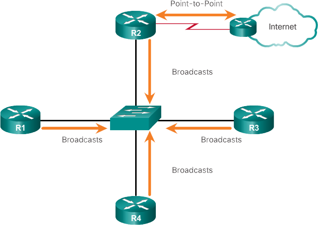
This article describe the OSPF DR BDR Election Process for different Types of OSPF networks.A multi-access network is a network with several devices on the same shared media, which share communications. Ethernet LANs are the most common example of multi-access networks with broadcast. In broadcast networks, all devices in the network can view all broadcast and multicast frames. They are multiple access networks since there can be a large number of hosts, printers, routers and other devices that are part of the same network.Types of OSPF networks
To configure OSPF settings, start with a basic implementation of the OSPF routing protocol.OSPF defines five types of networks, as shown in Images 1 to 5:
- Point to point : two routers interconnected by means of a common link. There are no other routers in the link. Frequently, this is the configuration on WAN links.

- Multiaccess with broadcast : several routers interconnected through an Ethernet network.

- Multi-access without broadcast (NBMA) : several routers interconnected in a network that does not allow broadcast transmissions, such as Frame Relay.

- Point to multipoint : several routers interconnected in a hub-and-spoke topology through an NBMA network. Often, it is used to connect branch sites (spokes, which means "lightning") to a central site (hub, which means "hub").

- Virtual links : a special OSPF network that is used to interconnect OSPF areas distant from the backbone area.


Challenges in multiple access networks
Multiple access networks can create two challenges for OSPF in relation to the saturation of LSAs:- Creating multiple adjacencies : Ethernet networks could interconnect many OSPF routers with a common link. The creation of adjacencies with each router is unnecessary and not recommended, as it would lead to the exchange of an excessive amount of LSA between routers in the same network.
- Intense saturation with LSA : Link state routers saturate with their link state packets when OSPF is initialized or when a change in the topology occurs. This saturation can become excessive.
OSPF DR Designated Router
The solution to manage the number of adjacencies and saturation with LSA in a multiple access network is the DR .In multiple access networks, OSPF chooses a DR to function as a collection and distribution point for the LSAs sent and received. A BDR is also chosen in case the DR fails. The BDR listens to this exchange passively and maintains a relationship with all routers. If the DR stops producing greeting packets, the BDR ascends itself and assumes the role of DR.
All other routers that are not DR or BDR become DROthers .
In Image, R1 was selected as the designated router of the Ethernet LAN that interconnects R2, R3 and R4. Notice how the number of adjacencies was reduced to three.

Routers in a multi-access network choose a DR and a BDR. DROthers only create complete adjacencies with the DR and BDR of the network. Instead of saturating all routers in the network with LSAs, DROthers only send their LSAs to the DR and the BDR via multicast address 224.0.0.6 (all DR routers).
OSPF DR function & how DR works

Note : The choice of DR / BDR only occurs in multiple access networks and not in point-to-point networks.
Verification of DR / BDR functions
In the multiple access topology shown in Image 10, there are three routers interconnected by means of a common Ethernet multiple access network, 192.168.1.0/28. Each router is configured with the IP address indicated on the Gigabit Ethernet 0/0 interface.
Because routers are connected through a multi-access network with common broadcast, OSPF automatically selected a DR and a BDR. In this example, R3 was chosen as the DR because the router ID is 3.3.3.3, which is the highest in the network. R2 is the BDR because it has the second highest router ID in the network.
Verification Commands
To verify the router's functions, use the show ip ospf interface command (Image 11). The result generated by R1 confirms the following:
- R1 is not the DR or the BDR, but a DROther with a default priority of 1. (1)
- The DR is R3 with router ID 3.3.3.3 at IP address 192.168.1.3, while BDR is R2 with router ID 2.2.2.2 at IP address 192.168.1.2. (2)
- R1 has two adjacencies: one with the BDR and one with the DR. (3)
The result generated by R2, in Image 12, confirms the following:

- R2 is the BDR, with a default priority of 1. (1)
- The DR is R3 with router ID 3.3.3.3 at IP address 192.168.1.3, while BDR is R2 with router ID 2.2.2.2 at IP address 192.168.1.2. (2)
- The R2 has two adjacencies, one with a neighbor that has router ID 1.1.1.1 (R1) and the other with the DR. (3)
The result generated by R3, in Image 13, confirms the following:

- R3 is the DR, with a default priority of 1. (1)
- The DR is R3 with router ID 3.3.3.3 at IP address 192.168.1.3, while BDR is R2 with router ID 2.2.2.2 at IP address 192.168.1.2. (2)
- The R3 has two adjacencies, one with a neighbor that has router ID 1.1.1.1 (R1) and the other with the BDR. (3)
Verification of adjacencies of DR / BDR
To verify OSPF adjacencies, use the show ip ospf neighbor command , as shown in Image 14.
Unlike serial links that only show a status of FULL / - , the status of neighbors in multiple access networks can be one of the following:
- FULL / DROTHER : This is a DR or BDR router that has full adjacency with a router that is not DR or BDR. These two neighbors can exchange greeting packages, updates, inquiries, responses and acknowledgments.
- FULL / DR : The router has full adjacency with the indicated DR neighbor. These two neighbors can exchange greeting packages, updates, inquiries, responses and acknowledgments.
- FULL / BDR : The router has full adjacency with the indicated BDR neighbor. These two neighbors can exchange greeting packages, updates, inquiries, responses and acknowledgments.
- 2-WAY / DROTHER : the router that is not DR or BDR has a neighbor relationship with another router that is not DR or BDR. These two neighbors exchange greeting packages.
In multiple access networks, DROthers only form FULL adjacencies with the DR and the BDR. However, they form 2-WAY neighbor adjacencies with any other DROther that joins the network.
Verification Results
The result generated by R1 confirms that it has adjacencies with the router:- The R2 with router ID 2.2.2.2 is in Full status and fulfills the function of BDR. (one)
- R3 with router ID 3.3.3.3 is in Full status and fulfills the function of DR. (2)

- R1 with router ID 1.1.1.1 is in Full state, and its function is not DR or BDR. (one)
- R3 with router ID 3.3.3.3 is in Full status and fulfills the function of DR. (2)

R1 with router ID 1.1.1.1 is in Full state, and its function is not DR or BDR. (one)
The R2 with router ID 2.2.2.2 is in Full status and fulfills the function of BDR. (2)
Default DR / BDR election process
How are DR and BDR selected? The decision to choose the DR and the BDR OSPF is made according to the following criteria, in sequential order:- Routers in the network select the router with the highest interface priority as DR . The router with the second highest interface priority is chosen as BDR.
The priority can be set to be any number between 0 and 255. The higher the priority, the more likely the router is chosen as DR. If the priority is set to 0, the router cannot become the DR.
The default priority of multiple access broadcast interfaces is 1. Therefore, unless configured otherwise, all routers have the same priority value and must depend on another differentiation method during the DR / election. BDR
- If the interface priorities are the same, the router with the highest ID is chosen as DR. The router with the second highest router ID is the BDR .
Remember that the router ID is determined in three ways:
- The router ID can be configured manually.
- If a router ID is not configured, the router ID is determined by the highest loopback IP address.
- If there are no loopback interfaces configured, the router ID is determined by the highest active IPv4 address.
Note : If there are no IPv4 addresses configured on the router in an IPv6 network, the router ID must be manually configured with the router-id id-router command; otherwise, OSPFv3 does not start.
DR Selection Example

In the illustration, all Ethernet interfaces of the router have a given priority of 1. As a result, according to the selection criteria described above, the ID of the OSPF router is used to select the DR and BDR.
R3, with the highest router ID, becomes the DR, and R2, which has the second highest router ID, becomes the BDR.
Note : Serial interfaces have the default priority set to 0; Therefore, they do not select DR or BDR.
The process of choosing the DR and the BDR occurs as soon as the first router with an interface with OSPF enabled is activated in the multiple access network. This can occur when the routers are turned on or when the OSPF network command is configured for that interface.
The election process only takes a few seconds. If all routers in the multi-access network have not finished booting, it is possible that a router with a lower router ID becomes the DR. (It can be a cheaper router that takes less time to boot).
DR / BDR election process
The choice of DR and BDR OSPF is not based on priority. If a new router with a higher priority or a higher router ID is added to the network after the choice of DR and BDR, the added router does not appropriate the DR or BDR function.This is because those functions have already been assigned. The incorporation of a new router does not initiate a new process of choice.
Once the DR is chosen, it remains as such until one of the following situations occurs:
- The DR fails.
- The OSPF process in the DR fails or stops.
- The multi-access interface in the DR fails or shuts down.
If the DR fails, the BDR is automatically promoted to DR. This happens even if another DROther with a higher priority or router ID is added to the network after the initial DR / BDR election. However, after the promotion of a BDR to DR, another BDR election is made and the DROther with the highest priority or router ID is chosen as the new BDR.
DR and BDR election process situations
In following images, the different situations related to the process of choosing DR and BDR are shown for your better understanding.- In Image following, the current DR (R3) fails, therefore, the preselected BDR (R2) assumes the function of DR. Next, the choice of the new BDR is made. Because R1 is the only DROther, it is selected as BDR.

- In Image, R3 joins the network again, after several minutes of being unavailable. Because the DR and the BDR already exist, the R3 does not occupy either function. Instead, it becomes a DROther

- In figure, a new router (R4) with a higher router ID is added to the network. DR (R2) and BDR (R1) retain their DR and BDR functions. The R4 automatically becomes DROther.

- If R2 fails. The BDR (R1) automatically becomes the DR, and a process of choice selects R4 as the BDR, since it has the highest router ID.


The OSPF DR Priority
The DR becomes the center of the collection and distribution of LSA, therefore, said router must have sufficient memory and CPU capacity to handle the workload. It is possible to influence the process of choosing DR / BDR through configurations.If the interface priorities are the same on all routers, the router with the highest ID is chosen as DR.
It is possible to configure the router ID to manipulate the DR / BDR choice. However, the process only works if there is a rigorous plan to establish the router ID of all routers. In large networks, this can be cumbersome.
Instead of relying on the router ID, it is better to control the choice by setting interface priorities. Priorities are a specific value of each interface, which means that they provide better control in a multi-access network. This also allows a router to be the DR in one network and a DROther in another.
To set the priority of an interface, use the following commands:
- ip ospf priority value - OSPFv2 interface command
- ipv6 ospf priority value - OSPFv3 interface command
The value can be one of the following:
- 0 : does not become DR or BDR.
- 1 to 255 : The higher the priority value, the more likely the router to become the DR or the BDR of the network.
OSPF priority example
In the illustration, all routers have the same OSPF priority, because the priority value is set to 1 for all router interfaces by default.
If the interface priority is set after enabling OSPF, the administrator must deactivate the OSPF process on all routers and then re-enable it to force a new DR / BDR choice.
Change of OSPF priority
In the topology of the Imagenanterior, R3 is the DR and R2 is the BDR. The following was decided:- R1 must be the DR and is configured with a priority of 255.
- R2 must be the BDR and the default priority of 1 is left.
- The R3 must never be a DR or BDR and is configured with a priority of 0.
Next, the priority of the Gigabit 0/0 interface of R1 is changed from 1 to 255.
R1 (config) # interface GigabitEthernet 0/0
R1 (config-if) # ip ospf priority 255
R1 (config-if) # end
R1 #
Now, the priority of the Gigabit 0/0 interface of R3 is changed from 1 to 0.
R3 (config) # interface GigabitEthernet 0/0
R3 (config-if) # ip ospf priority 0
R3 (config-if) # end
R3 #
The changes have no effect automatically, because the DR and BDR have already been selected. Therefore, the choice of OSPF must be negotiated by one of the following methods:
- Disable the router interfaces and re-enable them one at a time: first the DR, then the BDR and then all other routers.
- Reset the OSPF process using the clear ip ospf process command in privileged EXEC mode on all routers.
In following image, we show how to delete the OSPF process in R1. Assume that the clear ip ospf process command of the privileged EXEC mode was also configured on R2 and R3. Observe the OSPF status information that is generated.

The result shown in Image confirms that R1 is now the DR, with a priority of 255, and identifies the new neighborhood adjacencies of R1.

Thank you for reading this, please share your feedback regarding article.
No comments:
Post a Comment