Showing posts with label ospf. Show all posts

Monday, 28 October 2019

Troubleshooting OSPF and OSPFv3 Single Area Commands

Troubleshooting OSPF and OSPFv3 Single Area Commands

Troubleshooting OSPF  is a very important topic for network engineers. While troubleshooting you must have understanding of Troubleshooting OSPF commands. When troubleshooting OSPF neighbors, be aware that the FULL or 2WAY states are normal. Commands for troubleshooting OSPF for IPv4 are discussed in detail. The troubleshooting of OSPFv3 is similar to that of OSPFv2, which you learn at the end of this post.

OSPF States

To solve OSPF problems, it is important to understand how OSPF routers go through different OSPF states when adjacencies are established.
In the illustration, the OSPF states are indicated and a summary of the functions of each state is provided.

Transition Table through OSPF states.
State
Description
Down state
No greeting package received = Down.
The router sends hello packets.
Transition to Init status.
Init Status
The neighbor's greeting packages are received.
These contain the sender router ID.
Transition to the Two-Way state.
Two-Way Status
On Ethernet links, a DR and a BDR are chosen.
Transition to ExStart state.
ExStart Status
The master / slave relationship and the sequence number of the DBD packet are negotiated.
The master starts the exchange of DBD packages.
Exchange Status
Routers exchange DBD packets.
If additional router information is required, the transition to Loading is made; otherwise, the transition to Full is made.
Loading status
LSRs and LSUs are used to obtain additional route information.
Routes are processed using the SPF algorithm.
Transition to the Full state.
Full state
The routers converged.
When troubleshooting OSPF neighbors, be aware that the FULL or 2WAY states are normal. All other states are temporary , that is, the router should not remain in those states for extended periods.

Commands for Troubleshooting OSPF

There are many different OSPF commands that can be used to facilitate the troubleshooting process. The following are the most common commands:

show ip protocols

It is used to verify fundamental OSPF configuration information, such as the OSPF process ID, the router ID, the networks announced by the router, the neighbors from which the router receives updates, and the default administrative distance, which for OSPF is 110 .

 show ip ospf neighbor

It is used to verify if the router formed an adjacency with neighboring routers.

  • It shows the ID of the neighbor router, the priority of the neighbor, the OSPF status, the timeout timer, the IP address of the neighboring interface and the interface through which the neighbor can be accessed.
  • If the neighbor router ID is not displayed or is not displayed in the FULL or 2WAY state, the two routers did not form an OSPF adjacency. If two routers did not establish adjacency, the link-state information will not be exchanged.
  • Incomplete link-state databases can create SPF trees and inaccurate routing tables. It is possible that there are no routes to the destination networks or they may not represent the most optimal route.

show ip ospf interface

It is used to display the OSPF parameters that were configured on an interface, such as the ID of the OSPF process to which the interface was assigned, the area in which the interfaces are located, the cost of the interface and the greeting and dead intervals .
If the name and interface number is added to the command, the result for a specific interface is displayed. Learn about OSPF Interface configurations

show ip ospf

It is used to examine the OSPF process ID and the router ID. In addition, this command shows OSPF area information and the last time the SPF algorithm was calculated.

show ip route ospf

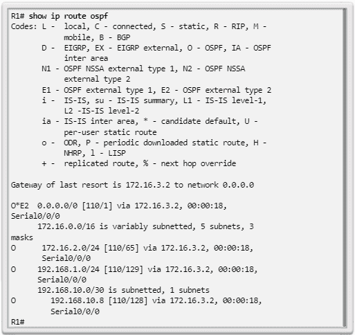
It is used to show only the OSPF routes discovered in the routing table. The result shows that R1 discovered about four remote networks through OSPF.
clear ip ospf [ process-id ] process : used to reset the adjacencies of OSPFv2 neighbors.

Components of OSPF troubleshooting

As shown in the illustration, in general, OSPF problems are related to one of the following aspects:

  • Adjacences of neighbors
  • Missing Routes
  • Route selection

When troubleshooting neighbors, verify if the router established adjacencies with neighboring routers using the show ip ospf neighbors command .

  • If there are no adjacencies, routers cannot exchange routes. Check if the interfaces work and are enabled for OSPF using the show ip interface brief and show ip ospf interface commands .
  • Now, if the interfaces work and are enabled for OSPF, make sure that the interfaces on both routers are configured for the same OSPF area and are not configured as passive interfaces.
  • If the adjacency between the two routers is established, verify that there are OSPF routes in the routing table using the show ip route ospf command.
  • If there are no OSPF routes, verify that there are no other routing protocols with lower administrative distances running on the network. Verify if all required networks are advertised in OSPF. Also check if there is an access list configured on a router that could filter incoming or outgoing routing updates.
If all the required routes are in the routing table but the route the traffic takes is incorrect, verify the OSPF cost of the interfaces on the route. Also, pay special attention in cases where the interfaces have a speed greater than 100 Mb / s, since all interfaces above this bandwidth have the same OSPF cost by default.

Solving single-area OSPF Routing problems

Troubleshooting OSPF Neighbors

In this example, we will demonstrate how to solve neighbor problems . In the topology of Image 9, all routers were configured to support OSPF routing.

A look at the routing table of R1, shown in following figure, lets us know that it does not add OSPF routes.
There are several possible reasons for this. However, a requirement for a neighbor relationship between two routers to form is the layer 3 connectivity of the OSI model.
The result of following image confirms that the S0 / 0/0 interface is active and functioning. The correct ping also confirms that the R2 serial interface is active. A correct ping does not mean that an adjacency will form, because there may be overlapping subnets.
You should still verify that the interfaces on the connected devices share the same subnet. If the ping was not correct, check the wiring and verify that the interfaces on the connected devices are configured correctly and work.

Enable an interface for OSPF

To enable an interface for OSPF, you must configure a network command that matches during the OSPF routing process. Active OSPF interfaces can be verified using the show ip ospf interface command . The result of Image 12 verifies that the Serial 0/0/0 interface is enabled for OSPF. If the interfaces connected on two routers are not enabled for OSPF, neighbors will not form an adjacency.

Verify the OSPF configuration using the show ip protocols command . The result shown in following Image verifies that OSPF is enabled and also lists the networks that are advertised as enabled through the network command. If an IP address on an interface is included in an OSPF-enabled network, the interface is enabled for OSPF.

Disable the interface as passive

However, note that the Serial 0/0/0 interface is listed as passive. Remember that the passive-interface command stops incoming and outgoing routing updates, because the effect of the command causes the router to stop sending and receiving hello packets through an interface. For this reason, routers will not form a neighbor relationship.
To disable the interface as passive, use the no passive-interface command of the router configuration mode, as shown in Image below. After disabling the passive interface, the routers establish an adjacency, as indicated by the generated information message automatically.

A quick check of the routing table, shown in following Image, confirms that OSPF now exchanges routing information.
Another problem that may arise is that two neighboring routers have incompatible MTU sizes on the connected interfaces .
The MTU size is the largest network layer packet that the router forwards through each interface. By default, routers have an MTU size of 1500 bytes. However, this value can be changed for IPv4 packets using the ip mtu size interface configuration command or the mv size ipv6 interface command for IPv6 packets.
If two connected routers had incompatible MTU values, they would also try to form an adjacency, but would not exchange their LSDBs and the neighbor relationship would fail.

Troubleshooting the OSPF routing table

In the illustration topology, all routers were configured to support OSPF routing.

A look at the routing table of R1 (shown in following image) allows us to know that it receives information from the default route, the R2 LAN (172.16.2.0/24) and the link between R2 and R3 (192.18.10.8/30 ). However, it does not receive the OSPF LAN route from R3.

The result of following Image verifies the OSPF configuration on R3. Note that R3 only announces the link between R3 and R2, but does not announce the R3 LAN (192.168.1.0/24).

To enable an interface for OSPF, you must configure a network command that matches during the OSPF routing process. The result of Image (show running config) confirms that the R3 LAN is not announced on OSPF.

The result of Image verifies that the R3 LAN is now in the R1 routing table.

Commands for troubleshooting OSPFv3

See the Illustration for the OSPFv3 reference topology.

The troubleshooting of OSPFv3 is almost identical to that of OSPFv2; Therefore, many OSPFv3 commands and troubleshooting criteria also apply to OSPFv3.
For example, the following are the equivalent commands used with OSPFv3:

show ipv6 protocols

This command is used to verify fundamental OSPFv3 configuration information, including the OSPFv3 process ID, the router ID and the interfaces from which the router receives updates

show ipv6 ospf neighbor

It is used to verify that the router formed an adjacency with neighboring routers.

  • This result shows the ID of the neighbor router, the priority of the neighbor, the status of OSPFv3, the timeout timer, the ID of the neighboring interface and the interface through which the neighbor can be accessed.
  • If the neighbor router ID is not shown or is not displayed in the FULL or 2WAY state, the two routers did not form an OSPFv3 adjacency.
  • If two routers did not establish adjacency, the link-state information will not be exchanged. Incomplete link-state databases can create SPF trees and inaccurate routing tables. It is possible that there are no routes to the destination networks or that these are not the best routes.

show ipv6 ospf interface

It is used to display the OSPFv3 parameters that were configured in an interface, such as the OSPFv3 process ID to which the interface was assigned, the area in which the interfaces are located, the interface cost and the greeting and dead intervals .
If the name and interface number is added to the command, the result for a specific interface is displayed.

show ipv6 ospf

It is used to examine the OSPF process ID and router ID, as well as information on LSA transmissions

show ipv6 route ospf

It is used to show only the OSPFv3 routes discovered in the routing table. The result shows that R1 discovered about four remote networks using OSPFv3.

OSPF Multi-Area Configuration & Summary Routes

Cisco OSPF Multi-Area Configuration & Summary Routes

This article is a complete step by step guide for OSPF Multi-Area Configuration & Summary Routes on Cisco Router. Also topology examples of multi-area OSPF v2 and OSPF v3 configuration are explained here. Following are some OSPF related articles:


Configuration of OSPF Multi-Area 

The OSPF implementation can be single or multi-area. The type of OSPF implementation chosen depends on the specific requirements and the existing topology.
To implement multi-area OSPF, four steps must be followed.
Steps 1 and 2 are part of the planning process.

  • Step 1. Collect network parameters and requirements : this includes determining the number of host and network devices, the IP addressing scheme (if already implemented), the size of the domain and routing tables, the risk of changes in the topology and other characteristics of the network.
  • Step 2. Define the OSPF parameters : Based on the information you collected in step 1, the network administrator must determine if the preferred implementation is single-area or multi-area OSPF. If multi-area OSPF is selected, the network administrator must consider the following:
    •  IP addressing plan : this governs the way in which OSPF can be implemented and how well the OSPF implementation could be scaled.
    •  OSPF Areas : The division of an OSPF network into areas decreases the size of the LSDB and limits the propagation of link state updates when the topology is modified. The routers that are going to fulfill the function of ABR and ASBR must be identified, as well as those that will carry out the summarization or redistribution.
    •  Network topology: this consists of links that connect the network equipment and that belong to different OSPF areas in a multi-area OSPF design. The network topology is important to determine the main and backup links.
  • Step 3 . Configure the multi-area OSPF implementation according to the parameters.
  • Step 4 . Verify the implementation of multi-area OSPF according to the parameters.

OSPF Configuration of Different Areas


In Figure 1, the multi-area OSPF reference topology is shown. In this example:

  • R1 is an ABR because it has interfaces in area 1 and an interface in area 0.
  • R2 is an internal backup router because all its interfaces are in area 0.
  • R3 is an ABR because it has interfaces in area 2 and an interface in area 0.

No special commands are required to implement this OSPF network from various areas. A router simply becomes ABR when it has two network instructions in different areas .

OSPF v2 Multi-Area Configuration Example

As shown below, router ID 1.1.1.1 was assigned to R1. This example activates OSPF on the two LAN interfaces in area 1.
The serial interface is configured as part of OSPF area 0. Since R2 has interfaces connected to two different areas, it is an ABR.
R1 (config) # router ospf 10
R1 (config-router) # router-id 1.1.1.1
R1 (config-router) # network 10.1.1.1 0.0.0.0 area 1
R1 (config-router) # network 10.1.2.1 0.0.0.0 area 1
R1 (config-router) # network 192.168.10.1 0.0.0.0 area 0
R1 (config-router) # end
R1 #
Multi-area OSPF is configured on R2 and the wildcard mask of the interface network address is used:
R2 (config) # router ospf 10
R2 (config-router) # router-id 2.2.2.2
R2 (config-router) # network 192.168.10.0 0.0.0.3 area 0
R2 (config-router) # network 192.168.10.4 0.0.0.3 area 0
R2 (config-router) # network 10.2.1.0 0.0.0.255 area 0
R2 (config-router) # end
R2 #
* Apr 19 18: 11: 04.029:% ​​OSPF-5-ADJCHG: Process 10, Nbr 1.1.1.1 on 
Serial0 / 0/0 from LOADING to FULL, Loading Done
R2 #
Then multi-area OSPF is configured on R3. Here the wildcard mask 0.0.0.0 is used for all networks.
R3 (config) # router ospf 10
R3 (config-router) # router-id 3.3.3.3
R3 (config-router) # network 192.168.10.6 0.0.0.0 area 0
R3 (config-router) # network 192.168.1.1 0.0.0.0 area 2
R3 (config-router) # network 192.168.2.1 0.0.0.0 area 2
R3 (config-router) # end
Apr 19 18: 12: 55,881:% OSPF-5-ADJCHG: Process 10, Nbr 2.2.2.2 on 
Serial0 / 0/1 from LOADING to FULL, Loading Done

OSPFv3 Configuration of various areas

As in OSPFv2, the implementation of the multi-area OSPFv3 topology of Image 2 is simple.

No special commands are required. A router becomes ABR when it has two interfaces in two different areas.

OSPFv3 Multi-Area Configuration Example

For example, in the scheme below, router ID 1.1.1.1 was assigned to R1. The example also enables OSPF on the two LAN interfaces in area 1 and on the serial interface in area 0. Since R1 has interfaces connected to two different areas, it is an ABR.
R1 (config) # ipv6 router ospf 10
R1 (config-rtr) # router-id 1.1.1.1
R1 (config-rtr) # exit
R1 (config) # 
R1 (config) # interface GigabitEthernet 0/0
R1 (config-if) # ipv6 ospf 10 area 1
R1 (config-if) # 
R1 (config-if) # interface Serial0 / 0/0
R1 (config-if) # ipv6 ospf 10 area 0
R1 (config-if) # end
R1 #
For R2, we enter the OSPFv3 router configuration mode with process ID 10 and configure router ID 2.2.2.2.
R2 (config) # ipv6 router ospf 10
* Apr 24 14: 18: 10,463:% OSPFv3-4-NORTRID: Process OSPFv3-10-IPv6 
could not pick a router-id, please configure manually
R2 (config-rtr) # router-id 2.2.2.2
R2 (config-rtr) # exit
Now, OSPFv3 is configured for process ID 10 on each of the interfaces:
R2 (config) # interface g0 / 0
R2 (config-if) # ipv6 ospf 10 area 0
R2 (config-if) # interface S0 / 0/0
R2 (config-if) # ipv6 ospf 10 area 0
R2 (config-if) # interface S0 / 0/1
R2 (config-if) # ipv6 ospf 10 area 0
R2 (config-if) # end
* Apr 24 14: 18: 35.135:% OSPFv3-5-ADJCHG: Process 10, Nbr 1.1.1.1 on 
Serial0 / 0/0 from LOADING to FULL, Loading Done
For R3, we enter the OSPFv3 router configuration mode with process ID 10 and configure router ID 3.3.3.3.
R3 (config) # ipv6 router ospf 10
* Apr 24 14: 20: 42.463:% OSPFv3-4-NORTRID: Process OSPFv3-10-IPv6 
could not pick a router-id, please configure manually
R3 (config-rtr) # router-id 3.3.3.3
R3 (config-rtr) # exit
And finally, OSPFv3 is configured for process ID 10 in each of the interfaces:
R3 (config) # interface g0 / 0
R3 (config-if) # ipv6 ospf 10 area 2
R3 (config-if) # interface S0 / 0/1
R3 (config-if) # ipv6 ospf 10 area 0
R3 (config-if) # end
* Apr 24 14: 21: 01.439:% OSPFv3-5-ADJCHG: Process 10, Nbr 2.2.2.2 on 
Serial0 / 0/1 from LOADING to FULL, Loading Done
R3 #

OSPF Summary Routes

The summary helps to make the routing tables shorter. It involves consolidating several routes into a single ad, which then spreads to the backbone area.
Typically, type 1 and type 2 LSAs are generated within each area , translated into type 3 LSAs and sent to other areas. If area 1 had thirty networks to announce, thirty Type 3 LSAs would be forwarded to the backbone network. With the route summary, the ABR consolidates the 30 networks into one of two advertisements.
In Image 3, R1 consolidates all network announcements in a summary LSA.

Instead of resending LSA individually for each route in area 1, R1 forwards a summary LSA to core router C1. C1, in turn, forwards the summary LSA to R2 and R3. R2 and R3 then forward it to their respective internal routers.
The summary also helps increase network stability, because it reduces unnecessary flooding of LSA.
This situation directly affects the amount of memory, CPU and bandwidth resources used by the OSPF routing process. Without a route summary, all specific link LSAs propagate on the OSPF backbone network and beyond, which generates unnecessary network traffic and router reload.
In Image, a network link on R1 fails. R1a sends an LSA to R1. However, R1 does not propagate the update, since it has a summary route configured. The saturation of specific links outside the area with LSA does not occur.

Summarization of external and inter-area routes

In OSPF, summarization can be configured only in ABRs or ASBRs. Instead of announcing many specific networks, ABR and ASBR routers announce a summary route. The ABR summary LSA type 3 routers and the ASBR summary LSA type 5 routers.
By default, summary LSAs (type 3 LSAs) and external LSAs (type 5) do not contain summary (aggregate) routes; that is, by default, summary LSAs are not summarized.

As shown in above Images , route summarization can be configured as follows:

  • Inter-area route summarization : inter-area route summarization occurs in the ABRs and is applied to routes within each area. It does not apply to external routes introduced in OSPF through redistribution.

To effectively summarize inter-area routes, network addresses must be assigned contiguously, so that these addresses can be summarized in a minimum number of summary addresses.

  • Summarization of external routes : the summarization of external routes is specific to the external routes that are introduced in OSPF through the redistribution of routes. Again, it is important to ensure the contiguity of the external address ranges that are summarized.

Usually, only ASBRs summarize external routes. As shown in Image 6, ASBR R2 summarizes the external EIGRP routes in a single LSA and sends them to R1 and R3.
Note : In ASBRs, the summarization of external routes is configured using the summary-address address mask command of the router configuration mode.

 Inter-area route summarization

OSPF does not perform automatic summarization. The inter-area summarization must be manually configured in the ABRs.
Only ABRs can summarize internal routes. When summarization is enabled in an ABR, a single type 3 LSA describing the summary route is introduced into the backbone. This unique LSA summarizes several routes within the area.
A summary route is generated if at least one subnet within the area is within the range of summary addresses. The summary route metric equals the lowest cost of all subnets within the range of summary addresses.

In Image, a multi-area OSPF topology is shown. The routing tables of R1 and R3 are analyzed to see the effect of summarization.

In Image below, the routing table of R1 is shown before summarization is configured, while in next Image , the routing table of R3 is shown.


Calculation of the summary route


The figure shows that the summary of networks in a single address and mask can be done in three steps:

  • Step 1 . List the networks in binary format. In the example, the two networks in area 1 (10.1.1.0/24 and 10.1.2.0/24) are indicated in binary format.
  • Step 2 . Count the number of bits that match on the far left to determine the summary path mask. As highlighted, the first 22 digits of the far left match. This produces the prefix / 22 or subnet mask 255.255.252.0.
  • Step 3 . Copy the matching bits and then add the zero bits to determine the summarized network address. In this example, the bits coinciding with leading zeros show us as a result the network address 10.1.0.0/22. This summary address brings together four networks: 10.1.0.0/24, 10.1.1.0/24, 10.1.2.0/24 and 10.1.3.0/24.

In the example, the summary address matches four networks although there are only two networks.

Inter-route summary configuration

In Image, to demonstrate the effect of route summarization, R1 is configured to summarize the internal routes of area 1.
To manually configure inter-route route summarization in an ABR, use the area area-id range address mask command in router configuration mode. This instructs the ABR to summarize the routes for a specific area before introducing them into another area in the form of LSA type 3 summary through the backbone.
Note : In OSPFv3, the command is identical, except for the IPv6 network address. The command syntax for OSPFv3 is area area id range prefix / prefix-length .
The two internal routes of area 1 are summarized below in an OSPF inter-area summary route on R1. The summary route 10.1.0.0/22 ​​summarizes four network addresses: from 10.1.0.0/24 to 10.1.3.0/24.
R1 (config) # router ospf 10
R1 (config-router) # area 1 range 10.1.0.0 255.255.252.0
R1 (config-router) #

OSPF Area and LSA Types Link state advertisement

OSPF Area and LSA Types

There are different types of OSPF Area and LSA Types. In this chapter you will learn all types of OSPF areas and Link state advertisement LSA.

Why Multiarea OSPF ?

Single area OSPF is useful in smaller networks , where the network of links between routers is simple and routes to individual destinations are easily deduced.
However, if an area grows too large, the following problems should be resolved immediately:


  • Extensive routing tables : OSPF does not summarize routes by default. If the routes are not summarized, the routing table becomes very large, depending on the size of the network.
  • Very large link state (LSDB) databases : because the LSDB covers the topology of the entire network, each router must maintain an entry for each network in the area, even if not all routes are selected for the table routing
  • Frequent calculations of the SPF algorithm : in large networks, modifications are inevitable, so routers spend many CPU cycles recalculating the SPF algorithm and updating the routing table.
To make OSPF more efficient and scalable, this protocol supports hierarchical routing through areas. An OSPF area is a group of routers that share the same link state information in the link state databases.

Multi-area OSPF

When a large OSPF area is divided into smaller areas, this is called " multi-area OSPF ". Multi-area OSPF is useful in larger network implementations , as it reduces processing and memory overhead.
For example, every time a router receives new information about the topology, such as adding, removing or modifying a link, the router must rerun the SPF algorithm, create a new SPF tree and update the routing table .
The SPF algorithm represents a high demand for the CPU and the time it takes to perform the calculations depends on the size of the area. If there were too many routers in an area, the LSDB would be larger and the CPU load would increase. Therefore, the arrangement of routers in different areas effectively divides a potentially large database into smaller and easier to manage databases.
Multi-area OSPF requires a hierarchical network design . The main area is called “backbone network” (area 0) and the rest of the areas must be connected to it. With hierarchical routing, inter-area routing continues to occur (inter-area routing), and many of the tedious routing operations, such as recalculating the database, are stored in an area.

Advantages of multi-area OSPF

As illustrated in Image 2, the possibilities of hierarchical topology of multi-area OSPF have the following advantages:


  • Smaller routing tables : there are fewer entries in the routing table, since network addresses can be summarized between areas. For example, R1 summarizes routes from area 1 to area 0 and R2 summarizes routes from area 51 to area 0. In addition, R1 and R2 propagate a predetermined static route to areas 1 and 51.
  • Lower link state update overhead : minimizes processing and memory requirements, since there are fewer routers that exchange LSA.
  • Lower frequency of SPF calculations: Locate the impact of a topology change within an area. For example, it minimizes the impact of a routing update, because LSA flooding stops at the area's border.

In Image, suppose a link between two internal routers in area 51 fails. Only routers in area 51 exchange LSA and rerun the SPF algorithm for this event. R1 does not receive the LSAs from area 51 and does not recalculate the SPF algorithm.


OSPF Two layer area hierarchy

The OSPF of various areas is implemented with a two-layer area hierarchy:

  • Trunk (transit) network area: an OSPF area whose main function is the fast and efficient transmission of IP packets.

Trunk network areas interconnect with other types of OSPF area. In general, end users are not in a backbone network area. The backbone area is also called "OSPF area 0". In hierarchical networks, area 0 is defined as the core to which all other areas are connected directly.

Common area (not backbone network) : connect users and resources. Regular areas are generally set up in functional or geographic groups. By default, a regular area does not allow traffic from another area to use its links to reach other areas. All traffic from other areas must pass through a transit area.
Note : Common areas may have a variety of subtypes, including a standard area, an internal route area, an exclusive internal route area and a non-exclusive internal route area (NSSA).
OSPF applies this rigid two-layer area hierarchy. The underlying physical connectivity of the network must be assigned to the structure of the two-layer area, with only non-backbone areas directly connected to area 0. All traffic that is transferred from one area to the other must cross the area backbone network.
This traffic is called " inter-area traffic ".

Cisco Recommendations

 The optimal number of routers per area depends on factors such as network stability, but Cisco recommends keeping the following guidelines in mind:

  • An area should not have more than 50 routers.
  • A router should not be in more than three areas.
  • No router must have more than 60 neighbors.

OSPF Router Types

Different types of OSPF routers control the traffic that enters and leaves the areas. OSPF routers are categorized according to the role they play in the routing domain .
There are four different types of OSPF routers:

  • Internal router : it is a router whose interfaces are all in the same area. All internal routers in an area have identical LSDBs.


  • Backbone router: It is a router that is in the backbone area. In general, the backbone network area is set to area 0.


Area Border router. (ABR) : It is a router whose interfaces connect to several areas. You must maintain an LSDB for each area to which you are connected; You can routing between areas. ABRs are exit points for each area. In a network of various areas, an area can have one or more ABRs.

Autonomous system Border router (ASBR) : a router that has at least one interface connected to an external internetwork (another autonomous system), for example, a non-OSPF network. An ASBR can import information from a non-OSPF network into an OSPF network, and vice versa, through a process called “route redistribution ”.
OSPF redistribution of various areas occurs when an ASBR connects different routing domains (for example, EIGRP and OSPF) and configures them to exchange and advertise routing information between said routing domains.

OSPF link State Advertisement LSA types

LSAs are the functional blocks of the OSPF LSDB . Individually, they function as database records and provide specific details of OSPF networks. Together, they describe the entire topology of an area or an OSPF network.
Currently, RFCs for OSPF specify up to 11 different types of LSAs (See table).
OSPF LSA Types Table.
LSA Type
Description
one
Router LSA
2
LSA of the network
3 and 4
Summary LSA
5
AS external LSA
6
OSPF multicast LSA
7
Defined for NSSAs
8
LSA of external attributes for the border gateway protocol (BGP)
9, 10 or 11
Opaque LSA
However, any multi-area OSPF implementation must support the first five LSAs: from LSA 1 to LSA 5. This topic focuses on these first five LSAs.
Every router link is defined as a type of LSA. The LSA comprises a link ID field that identifies, by number and netmask, the object to which the link is connected. Depending on the type, the link ID has different meanings. LSAs vary depending on how they were generated and propagated within the routing domain.
Note : OSPFv3 includes additional types of LSA.

OSPF Type 1 LSA

As shown in the figure, every router announces its OSPF links with direct connection through a type 1 LSA and forwards the information from its network to the OSPF neighbors. The LSA contains a list of interfaces with direct connection, link types and link states.


Type 1 LSAs are also referred to as "router link entries."
Type 1 LSAs only flood the area that originates them. ABRs, at the same time, announce to other areas the networks discovered from type 1 LSAs as type 3 LSAs.
The router ID that originates the area identifies the link ID of a type 1 LSA.

OSPF Type 2 LSA

A type 2 LSA only exists for networks of various accesses and networks without diverse accesses or broadcast (NBMA) where a DR is selected and at least two routers in the segment of various accesses.

  • The type 2 LSA contains the router ID and DR IP address, in addition to the router ID of all other routers in the multiple access segment. A type 2 LSA is created for each multiple access network in the area.
  • The purpose of a Type 2 LSA is to provide other routers with information about multiple access networks within the same area.
  • The DR floods type 2 LSAs only in the area in which they originate. Type 2 LSAs are not forwarded outside the area.

Type 2 LSAs are also called "network link entries."

As shown in the figure, ABR1 is the DR of the Ethernet network of area 1. It generates LSA of type 2 and forwards them to area 1. ABR2 is the DR of the network of various accesses of area 0. There are no networks of various accesses in area 2; therefore, type 2 LSAs will never be propagated in that area.
The link status ID for a network LSA is the IP address of the DR interface that announces it.

Type 3 OSPF LSA

ABRs use Type 3 LSAs to advertise networks in other areas.
ABRs collect type 1 LSAs in the LSDB. After an OSPF area converges, the ABR creates a type 3 LSA for each recognized OSPF network. Therefore, an ABR with several OSPF routes must create a type 3 LSA for each network.
As shown in the figure, ABR1 and ABR2 propagate type 3 LSAs from one area to another.

ABRs propagate type 3 LSAs to other areas. During an important OSPF implementation with many networks, the spread of type 3 LSAs can cause significant flood problems. For this reason, it is strongly recommended that you manually configure the route summary in the ABR .

  • The link status ID is set to the network number, and the mask is also announced.
  • Receiving type 3 LSAs in your area does not prompt the router to execute the SPF algorithm. Routers that are advertised in type 3 LSAs are added to the router routing table or removed from it as appropriate, but the full SPF calculation is not required.

OSPF Type 4 LSA

Type 4 and type 5 LSAs are used together to identify an ASBR and advertise external networks that reach an OSPF routing domain.
The ABR generates a type 4 summary LSA only when there is an ASBR in the area. A type 4 LSA identifies the ASBR and assigns it a route . All traffic destined for an external autonomous system requires knowledge of the routing table of the ASBR that originated the external routes.

As shown in the illustration, the ASBR sends a type 1 LSA to identify itself as ASBR.
The LSA includes a special bit called an "external bit" (e bit) that is used to identify the router as an ASBR.

  • When ABR1 receives the type 1 LSA, it recognizes the e bit, generates a type 4 LSA and propagates it to the backbone network (area 0).
  • Subsequent ABRs propagate the type 4 LSA to other areas.
  • The link status ID is set in the ASBR router ID.

OSPF type 5 LSA

External type 5 LSAs announce routes to networks outside the autonomous OSPF system . These originate in the ASBR and spread to the entire autonomous system.
Type 5 LSAs are also known as external LSA inputs of the autonomous system.


  • In the figure, the ASBR generates LSA type 5 for each external route and propagates them to the area.
  • Subsequent ABRs also propagate type 5 LSAs to other areas.
  • Routers in other areas use LSA type 4 information to reach external routes.
During a large OSPF implementation with many networks, the spread of type 5 LSAs can cause significant flood problems. For this reason, it is strongly recommended that you manually configure the route summary in the ASBR .
The link status ID is the external network number.

OSPF Routing Table Entries

In Image 14, an example routing table is provided for a multi-area OSPF topology with a link to an external network that is not OSPF. OSPF routes in an IPv4 routing table are identified by the following descriptors:


  • Or : Router (type 1) and network (type 2) LSAs describe the details within an area. The routing table reflects this link status information with the designation O, which means that the route is intra-area.
  • IA O : When an ABR receives summary LSA, it adds them to its LSDB and rebuilds them in the local area.

When an ABR receives an external LSA, it adds it to its LSDB and propagates it in the area. Then, the internal routers assimilate the information in their database. Summary LSAs appear in the routing table as IA (inter-area routes).

  • O E1 or O E2 : in the routing table, external LSAs are marked as external routes type 1 (E1) or external routes type 2 (E2).

In Image, an IPv6 routing table is shown with inter-area, external and OSPF router routing table entries.

SPF Calculation OSPF Router

Each router uses the SPF algorithm under the LSDB to create an SPF tree. The SPF tree is used to determine the best routes.

As shown in the figure, the order in which the best routes are calculated is as follows:

  1. Every router calculates the best routes to destinations in your area (intra-area) and adds these entries to the routing table. These are type 1 and type 2 LSAs, which are indicated in the routing table with the designator "O". (one)
  2. Every router calculates the best routes to other areas in the internetwork. The best routes are the inter-area route entries, or LSA type 3 and type 4, and are indicated by the routing designator "O IA". (2)
  3. Every router (except those located in a form of internal routes) calculates the best routes to destinations of the external autonomous system (type 5). These are indicated by the route designator O E1 or O E2, depending on the configuration. (3)

When converging, a router communicates with any network inside or outside the autonomous OSPF system.