Showing posts with label ipv6. Show all posts

Monday, 28 October 2019

Troubleshooting OSPF and OSPFv3 Single Area Commands

Troubleshooting OSPF and OSPFv3 Single Area Commands

Troubleshooting OSPF  is a very important topic for network engineers. While troubleshooting you must have understanding of Troubleshooting OSPF commands. When troubleshooting OSPF neighbors, be aware that the FULL or 2WAY states are normal. Commands for troubleshooting OSPF for IPv4 are discussed in detail. The troubleshooting of OSPFv3 is similar to that of OSPFv2, which you learn at the end of this post.

OSPF States

To solve OSPF problems, it is important to understand how OSPF routers go through different OSPF states when adjacencies are established.
In the illustration, the OSPF states are indicated and a summary of the functions of each state is provided.

Transition Table through OSPF states.
State
Description
Down state
No greeting package received = Down.
The router sends hello packets.
Transition to Init status.
Init Status
The neighbor's greeting packages are received.
These contain the sender router ID.
Transition to the Two-Way state.
Two-Way Status
On Ethernet links, a DR and a BDR are chosen.
Transition to ExStart state.
ExStart Status
The master / slave relationship and the sequence number of the DBD packet are negotiated.
The master starts the exchange of DBD packages.
Exchange Status
Routers exchange DBD packets.
If additional router information is required, the transition to Loading is made; otherwise, the transition to Full is made.
Loading status
LSRs and LSUs are used to obtain additional route information.
Routes are processed using the SPF algorithm.
Transition to the Full state.
Full state
The routers converged.
When troubleshooting OSPF neighbors, be aware that the FULL or 2WAY states are normal. All other states are temporary , that is, the router should not remain in those states for extended periods.

Commands for Troubleshooting OSPF

There are many different OSPF commands that can be used to facilitate the troubleshooting process. The following are the most common commands:

show ip protocols

It is used to verify fundamental OSPF configuration information, such as the OSPF process ID, the router ID, the networks announced by the router, the neighbors from which the router receives updates, and the default administrative distance, which for OSPF is 110 .

 show ip ospf neighbor

It is used to verify if the router formed an adjacency with neighboring routers.

  • It shows the ID of the neighbor router, the priority of the neighbor, the OSPF status, the timeout timer, the IP address of the neighboring interface and the interface through which the neighbor can be accessed.
  • If the neighbor router ID is not displayed or is not displayed in the FULL or 2WAY state, the two routers did not form an OSPF adjacency. If two routers did not establish adjacency, the link-state information will not be exchanged.
  • Incomplete link-state databases can create SPF trees and inaccurate routing tables. It is possible that there are no routes to the destination networks or they may not represent the most optimal route.

show ip ospf interface

It is used to display the OSPF parameters that were configured on an interface, such as the ID of the OSPF process to which the interface was assigned, the area in which the interfaces are located, the cost of the interface and the greeting and dead intervals .
If the name and interface number is added to the command, the result for a specific interface is displayed. Learn about OSPF Interface configurations

show ip ospf

It is used to examine the OSPF process ID and the router ID. In addition, this command shows OSPF area information and the last time the SPF algorithm was calculated.
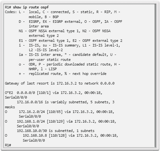
show ip route ospf

It is used to show only the OSPF routes discovered in the routing table. The result shows that R1 discovered about four remote networks through OSPF.
clear ip ospf [ process-id ] process : used to reset the adjacencies of OSPFv2 neighbors.

Components of OSPF troubleshooting

As shown in the illustration, in general, OSPF problems are related to one of the following aspects:

  • Adjacences of neighbors
  • Missing Routes
  • Route selection

When troubleshooting neighbors, verify if the router established adjacencies with neighboring routers using the show ip ospf neighbors command .

  • If there are no adjacencies, routers cannot exchange routes. Check if the interfaces work and are enabled for OSPF using the show ip interface brief and show ip ospf interface commands .
  • Now, if the interfaces work and are enabled for OSPF, make sure that the interfaces on both routers are configured for the same OSPF area and are not configured as passive interfaces.
  • If the adjacency between the two routers is established, verify that there are OSPF routes in the routing table using the show ip route ospf command.
  • If there are no OSPF routes, verify that there are no other routing protocols with lower administrative distances running on the network. Verify if all required networks are advertised in OSPF. Also check if there is an access list configured on a router that could filter incoming or outgoing routing updates.
If all the required routes are in the routing table but the route the traffic takes is incorrect, verify the OSPF cost of the interfaces on the route. Also, pay special attention in cases where the interfaces have a speed greater than 100 Mb / s, since all interfaces above this bandwidth have the same OSPF cost by default.

Solving single-area OSPF Routing problems

Troubleshooting OSPF Neighbors

In this example, we will demonstrate how to solve neighbor problems . In the topology of Image 9, all routers were configured to support OSPF routing.

A look at the routing table of R1, shown in following figure, lets us know that it does not add OSPF routes.
There are several possible reasons for this. However, a requirement for a neighbor relationship between two routers to form is the layer 3 connectivity of the OSI model.
The result of following image confirms that the S0 / 0/0 interface is active and functioning. The correct ping also confirms that the R2 serial interface is active. A correct ping does not mean that an adjacency will form, because there may be overlapping subnets.
You should still verify that the interfaces on the connected devices share the same subnet. If the ping was not correct, check the wiring and verify that the interfaces on the connected devices are configured correctly and work.

Enable an interface for OSPF

To enable an interface for OSPF, you must configure a network command that matches during the OSPF routing process. Active OSPF interfaces can be verified using the show ip ospf interface command . The result of Image 12 verifies that the Serial 0/0/0 interface is enabled for OSPF. If the interfaces connected on two routers are not enabled for OSPF, neighbors will not form an adjacency.

Verify the OSPF configuration using the show ip protocols command . The result shown in following Image verifies that OSPF is enabled and also lists the networks that are advertised as enabled through the network command. If an IP address on an interface is included in an OSPF-enabled network, the interface is enabled for OSPF.

Disable the interface as passive

However, note that the Serial 0/0/0 interface is listed as passive. Remember that the passive-interface command stops incoming and outgoing routing updates, because the effect of the command causes the router to stop sending and receiving hello packets through an interface. For this reason, routers will not form a neighbor relationship.
To disable the interface as passive, use the no passive-interface command of the router configuration mode, as shown in Image below. After disabling the passive interface, the routers establish an adjacency, as indicated by the generated information message automatically.

A quick check of the routing table, shown in following Image, confirms that OSPF now exchanges routing information.

Another problem that may arise is that two neighboring routers have incompatible MTU sizes on the connected interfaces .
The MTU size is the largest network layer packet that the router forwards through each interface. By default, routers have an MTU size of 1500 bytes. However, this value can be changed for IPv4 packets using the ip mtu size interface configuration command or the mv size ipv6 interface command for IPv6 packets.
If two connected routers had incompatible MTU values, they would also try to form an adjacency, but would not exchange their LSDBs and the neighbor relationship would fail.

Troubleshooting the OSPF routing table

In the illustration topology, all routers were configured to support OSPF routing.

A look at the routing table of R1 (shown in following image) allows us to know that it receives information from the default route, the R2 LAN (172.16.2.0/24) and the link between R2 and R3 (192.18.10.8/30 ). However, it does not receive the OSPF LAN route from R3.

The result of following Image verifies the OSPF configuration on R3. Note that R3 only announces the link between R3 and R2, but does not announce the R3 LAN (192.168.1.0/24).

To enable an interface for OSPF, you must configure a network command that matches during the OSPF routing process. The result of Image (show running config) confirms that the R3 LAN is not announced on OSPF.

The result of Image verifies that the R3 LAN is now in the R1 routing table.

Commands for troubleshooting OSPFv3

See the Illustration for the OSPFv3 reference topology.

The troubleshooting of OSPFv3 is almost identical to that of OSPFv2; Therefore, many OSPFv3 commands and troubleshooting criteria also apply to OSPFv3.
For example, the following are the equivalent commands used with OSPFv3:

show ipv6 protocols

This command is used to verify fundamental OSPFv3 configuration information, including the OSPFv3 process ID, the router ID and the interfaces from which the router receives updates

show ipv6 ospf neighbor

It is used to verify that the router formed an adjacency with neighboring routers.

  • This result shows the ID of the neighbor router, the priority of the neighbor, the status of OSPFv3, the timeout timer, the ID of the neighboring interface and the interface through which the neighbor can be accessed.
  • If the neighbor router ID is not shown or is not displayed in the FULL or 2WAY state, the two routers did not form an OSPFv3 adjacency.
  • If two routers did not establish adjacency, the link-state information will not be exchanged. Incomplete link-state databases can create SPF trees and inaccurate routing tables. It is possible that there are no routes to the destination networks or that these are not the best routes.

show ipv6 ospf interface

It is used to display the OSPFv3 parameters that were configured in an interface, such as the OSPFv3 process ID to which the interface was assigned, the area in which the interfaces are located, the interface cost and the greeting and dead intervals .
If the name and interface number is added to the command, the result for a specific interface is displayed.

show ipv6 ospf

It is used to examine the OSPF process ID and router ID, as well as information on LSA transmissions

show ipv6 route ospf

It is used to show only the OSPFv3 routes discovered in the routing table. The result shows that R1 discovered about four remote networks using OSPFv3.

Sunday, 27 October 2019

Configuration of Default Routes OSPF v2 and OSPFv3

Configuration of Default Routes OSPF v2 and OSPFv3

OSPF can be configured in many ways. This section explains the propagation and Configuration of default routes in OSPFv2 and OSPFv3. You will learn how to configure default static route with OSPF

Configurationof a default static route in OSPFv2

With OSPF, the router connected to the Internet is used to propagate a default route to other routers in the OSPF routing domain. This router is sometimes called a perimeter, gateway or gateway router .
However, in OSPF terminology, the router located between an OSPF routing domain and a non-OSPF network is also called an " autonomous system boundary router " (ASBR). configuration of OSPF Single area

In Image, R2 has a simple connection to a service provider. Therefore, all that is required for the R2 to reach the Internet is a default static route to the service provider.
Note : in this example, to simulate the connection to the service provider, a loopback interface with the IP address 209.165.200.225 is used.

OSPFv2 Default route settings

To propagate a default route, the perimeter router (R2) must be configured with the following:
A default static route, using the ip route 0.0.0.0 0.0.0.0 {ip-address | interface-exit} .
The default-information originate command of the router configuration mode. This instructs R2 to be the source of the default route information and propagate the default static route in OSPF updates.
The following shows how to configure a completely specified default static route to the service provider.
R2 (config) # ip route 0.0.0.0 0.0.0.0 209.165.200.226
R2 (config) #
R2 (config) # router ospf 10
R2 (config-router) # default-information originate
R2 (config-router) # end
R2 #

Verification of the propagated default route

Verify the default route configuration on R2 using the show ip route command , as shown in Image 2.


In following images, it is verified that the default route has been propagated to R1 and R3. Note that the origin of the route is O * E2, which specifies that it was discovered by OSPF. The asterisk indicates that this route is a good candidate for the default route. The designation "E2" indicates that it is an external route.


External routes can be external type 1 or external type 2. The difference between both types is the way in which the cost (metric) of the route is calculated.
The cost of a type 2 route is always the external cost, regardless of the internal cost to reach that route. Type 1 cost is the sum of the external cost and the internal cost necessary to reach that route. For the same destination, a type 1 route is always preferred to a type 2 route.

Configuration of a default static route in OSPFv3

The propagation process of a default static route in OSPFv3 is almost identical to that of OSPFv2.
In Image, R2 has a simple connection to a service provider. Therefore, all that is required for the R2 to reach the Internet is a default static route to the service provider.

Note : In this example, to simulate the connection to the service provider, a loopback interface with the IP address 2001: DB8: FEED: 1 :: 1/64 is used.
In following figure, the current IPv6 routing table of R1 is shown. Note that in this table there is no record that the route to the Internet is known.

 OSPFv3 default route settings

To propagate a default route, the perimeter router (R2) must be configured with the following:
A default static route, using the ipv6 route :: / 0 {ipv6-address | interface-exit} .
The command d efault-information originate from the router configuration mode. This instructs R2 to be the source of the default route information and propagate the default static route in OSPF updates.
Next, a completely specified default static route is configured to the service provider.
R2 (config) # ipv6 route :: / 0 2001: DB8: FEED: 1 :: 2
R2 (config) # 
R2 (config) # ipv6 router ospf 10
R2 (config-rtr) # default-information originate 
R2 (config-rtr) # end
R2 # 
* Jan 10 11: 36: 21.995:% SYS-5-CONFIG_I: Configured from console by console
R2 #

Verification of the propagated IPv6 default route

Verify the default static route configuration on R2 using the show ipv6 route command, as shown in Image 7.

In Images, it is verified that the default route has been propagated to R1 and R3. Note that the source of the route is OE2, which specifies that it was discovered using OSPFv3. The designation " E2 " indicates that it is an external route.


Unlike the IPv4 routing table, IPv6 does not use the asterisk to indicate that the route is a good candidate for the default route.

Sunday, 20 October 2019

DHCPv6 Troubleshooting Commands Cisco

DHCPv6 Troubleshooting Commands Cisco


This section explores the methods of DHCPv6 Troubleshooting with Cisco Commands. The problem solving process of DHCPv6 is similar to the resolution of DHCPv4 . Also, due to the number of potentially problematic areas, a systematic approach to problem solving is required, as shown in the following table:
Task No.
Description
Task 1 of troubleshooting:
Resolve address conflicts.
Task 2 of troubleshooting:
Verify physical connectivity.
Task 3 of troubleshooting:
Test with a static IPv6 address.
Task 4 of troubleshooting:
Verify switch port configuration.
Task 5 of troubleshooting:
Test from the same subnet or VLAN.
DHCPv6 Troubleshooting Table.

 Troubleshooting tasks (DHCPv6)

Here are some task and method for DHCPv6  troubleshooting. If you want to learn about DHCPv4 troubleshooting and how to configure DHCPv6 on Cisco, you can following these links:

  • Task 1: resolve conflicts

Similar to what happens with IPv4 addresses, leasing an IPv6 address may expire on a client that still needs to connect to the network. The show ipv6 dhcp conflict command   shows all address conflicts that the DHCPv6 server registers with status. If an IPv6 address conflict is detected, the client usually removes the address and generates a new one through SLAAC or with DHCPv6 with status.

  • TASK 2: VERIFY THE ALLOCATION METHOD

The  show ipv6 interface interface  command  can be used to verify the address assignment method that appears in the RA message, as indicated by the configuration of the M and O indicators. This information is shown in the last lines of the result. If a client does not receive the IPv6 address information from a DHCPv6 server with status, this could be due to incorrect M and O indicators in the RA message.

  • TASK 3: TEST WITH A STATIC IPV6 ADDRESS

By resolving any DHCP problem, whether DHCPv4 or DHCPv6, network connectivity can be verified by configuring a static IP address on a client workstation. In the case of IPv6, if the workstation cannot reach network resources with a statically configured IPv6 address, the root cause of the problem is not SLAAC or DHCPv6. At this point, it is necessary to solve network connectivity problems.

  • TASK 4: VERIFY SWITCH PORT CONFIGURATION

If the DHCPv6 client cannot obtain information from a DHCPv6 server, verify that the switch port is enabled and functioning correctly.

  • TASK 5: TEST THE OPERATION OF DHCPV6 ON THE SAME SUBNET OR VLAN

If the DHCPv6 server with status or without status is functioning correctly but is located on a VLAN or IPv6 network other than that of the client, it is possible that the problem is the DHCPv6 relay agent. The client that interacts with the interface on the router must be configured with the ipv6 dhcp relay destination command  .

Verification of the router's DHCPv6 configuration

Router configurations for DHCPv6 state and stateless services have many similarities, but also include significant differences. The following are the configuration commands for the two types of DHCPv6 services.

USING DHCPV6 WITH STATUS

Routers configured for DHCPv6 services with status have the address prefix command   to provide addressing information.
R1 (config) # ipv6 unicast-routing
R1 (config) # ipv6 dhcp pool IPV6-STATEFUL
R1 (config-dhcpv6) # address prefix 2001: DB8: CAFE: 1 :: / 64 lifetime 
infinite
R1 (config-dhcpv6) # dns-server 2001: db8: cafe: aaaa :: 5
R1 (config-dhcpv6) # domain-name example.com
R1 (config-dhcpv6) # exit
R1 (config) # interface g0 / 1
R1 (config-if) # ipv6 address 2001: db8: cafe: 1 :: 1/64
R1 (config-if) # ipv6 dhcp server IPV6-STATEFUL
R1 (config-if) # ipv6 nd managed-config-flag
For DHCPv6 services with status, the ipv6 nd managed-config-flag interface configuration mode command is used  . In this case, the client omits the routing information in the RA message and communicates with a DHCPv6 server to obtain addressing information and other information.

USING DHCPV6 WITHOUT STATUS

For stateless DHCPv6 services, the ipv6 nd other-config-flag interface configuration mode command is used  . This informs the device to use SLAAC for addressing information and a stateless DHCPv6 server for other configuration parameters.
R1 (config) # ipv6 unicast-routing
R1 (config) # ipv6 dhcp pool IPV6-STATELESS
R1 (config-dhcpv6) # dns-server 2001: db8: cafe: aaaa :: 5
R1 (config-dhcpv6) # domain-name example.com
R1 (config-dhcpv6) # exit
R1 (config) # interface g0 / 1
R1 (config-if) # ipv6 address 2001: db8: cafe: 1 :: 1/64
R1 (config-if) # ipv6 dhcp server IPV6-STATELESS
R1 (config-if) # ipv6 nd other-config-flag
The show ipv6 interface command   can be used to view the current configuration to determine the allocation method. As shown in the following scheme, the last line of the result indicates the way in which customers obtain addresses and other parameters.
SLAAC
R1 # show ipv6 interface g0 / 1
 GigabitEthernet0 / 1 is up, line protocol is up
 IPv6 is enabled, link-local address is
 FE80 :: D68C: B5FF: DATE: A0C1
DHCP without status

R1 # show ipv6 interface g0 / 1
 GigabitEthernet0 / 1 is up, line protocol is up
 IPv6 is enabled, link-local address is
 FE80 :: D68C: B5FF: DATE: A0C1
DHCP with status

R1 # show ipv6 interface g0 / 1
GigabitEthernet0 / 1 is up, line protocol is up
 IPv6 is enabled, link-local address is 
 FE80 :: D68C: B5FF: DATE: A0C1 

Debugging DHCPv6

When the router is configured as a DHCPv6 server with status or without status, the debug ipv6 dhcp detail command is useful for verifying the reception and transmission of DHCPV6 messages. As shown in the illustration, a DHCPv6 router with status received a REQUEST message from a client. The router uses the addressing information in its IPV6-STATEFUL pool for allocation information.
R1 # debug ipv6 dhcp detail
 IPv6 DHCP debugging is on (detailed)
R1 # 
* Feb 3 21: 27: 41.123: IPv6 DHCP: Received SOLICIT from 
FE80 :: 32F7: DFF: FE25: 2DE1 on GigabitEthernet0 / 1
* Feb 3 21: 27: 41.123: IPv6 DHCP: detailed packet contents
* Feb 3 21: 27: 41.123: src FE80 :: 32F7: DFF: FE25: 2DE1
(GigabitEthernet0 / 1)
* Feb 3 21: 27: 41.127: dst FF02 :: 1: 2
* Feb 3 21: 27: 41.127: type SOLICIT (1), xid 13190645
* Feb 3 21: 27: 41.127: option ELAPSED-TIME (8), len 2
* Feb 3 21: 27: 41.127: elapsed-time 0
* Feb 3 21: 27: 41.127: option CLIENTID (1), len 10
* Feb 3 21: 27: 41,127: 000
* Feb 3 21: 27: 41.127: IPv6 DHCP: Using interface pool IPV6- 
STATEFUL 
* Feb 3 21: 27: 41.127: IPv6 DHCP: Creating binding for 
FE80 :: 32F7: DFF: FE25: 2DE1 in pool IPV6-STATEFUL 
<Se skipped the result>

DHCPv6 Configuration On Cisco Router

DHCPv6 Configuration On Cisco Router

In this post you will learn DHCPv6 Configuration On Cisco Router. We will share command and topology example for better understanding. If you want to learn about what is DHCPv4 and how to configure DHCPv4 on Cisco, You can visit here. This post is purely related to DHCPv6 Configuration On Cisco Router.

Configure a router as a stateless DHCPv6 server

As will be shown below, there are four steps to configure a router as a DHCPv6 server:

  • Step 1: Enable IPv6 routing

The use of the ipv6 unicast-routing command is required to enable IPv6 routing. This command is not necessary for the router to be a stateless DHCPv6 server, but it is required for the router to originate the ICMPv6 RA messages.
Router (config) # ipv6 unicast-routing

  • Step 2: Configure a DHCPv6 pool

The ipv6 dhcp pool set-name creates a set and the router enters the DHCPv6 configuration command, which is identified by the Router line (config-dhcpv6) #.
Router (config) # ipv6 dhcp pool  pool-name 
Router (config-dhcpv6) #

  • Step 3: Configure the pool parameters

During the SLAAC process, the client received the information he needed to create a global unicast IPv6 address. The client also received the default gateway information through the source IPv6 address of the RA message, which is the router's link-local address. However, the stateless DHCPv6 server can be configured to provide other information that may not have been included in the RA message, such as the DNS server address and domain name.
Router (config-dhcpv6) # dns-server  dns-server-address 
Router (config-dhcpv6) # domain-name  domain-name

  • Step 4: Configure the DHCPv6 interface

The ipv6 dhcp server interface-configuration mode set-name links the DHCPv6 set with the interface. The router responds to DHCPv6 requests without status on this interface with the information included in the pool. The O indicator must be changed from 0 to 1 using the ipv6 nd other-config-flag interface command . RA messages sent on this interface indicate that additional information is available from a stateless DHCPv6 server.

Router (config) # interface type number
Router (config-if) # ipv6 dhcp server pool-name
Router (config-if) # ipv6 nd other-config-flag

SAMPLE DHCPV6 SERVER WITHOUT STATUS

In Image 1 together with the commands, an example configuration is shown for a router to be configured as a stateless DHCPv6 server. Note that router R3 is shown as a DHCPv6 client. R3 is configured as a client to help verify stateless DHCPv6 operations.

R1 (config) # ipv6 unicast-routing
R1 (config) # ipv6 dhcp pool IPV6-STATELESS
R1 (config-dhcpv6) # dns-server 2001: db8: cafe: aaaa :: 5
R1 (config-dhcpv6) # domain-name example.com
R1 (config-dhcpv6) # exit
R1 (config) # interface g0 / 1
R1 (config-if) # ipv6 address 2001: db8: cafe: 1 :: 1/64
R1 (config-if) # ipv6 dhcp server IPV6-STATELESS
R1 (config-if) # ipv6 nd other-config-flag

 Configure a router as a stateless DHCPv6 client

Following the example in Image 1, a Cisco router is used as the stateless DHCPv6 client. This is not a typical situation and is used only for demonstration purposes. Generally, a stateless DHCPv6 client is a device, such as a computer, a tablet PC, a mobile device or a webcam.
The client router needs a link-local IPv6 address on the interface to send and receive IPv6 messages, such as RS messages and DHCPv6 messages. The link-local address of a router is created automatically when IPv6 is enabled on the interface. This can happen when a global unicast address is configured on the interface or when the ipv6 enable command is used  . After the router receives a local link address, it can participate in the detection of IPv6 neighbors.
In this example, the ipv6 enable command is used  , because the router does not yet have a global unicast address.
R3 (config) # interface g0 / 1
R3 (config-if) # ipv6 enable
R3 (config-if) # ipv6 address autoconfig
R3 (config-if) #
The ipv6 address autoconfig command   enables automatic configuration of IPv6 addressing using SLAAC. It is assumed that the server router is configured for stateless DHCPv6, so it sends an RA message to inform the client router that it uses stateless DHCPv6 to obtain DNS information.

Verification of DHCPv6 without status

Continuing with the example in Image 1, the show ipv6 dhcp pool  command  verifies the name of the DHCPv6 pool and its parameters. The number of active clients is 0, because the server does not maintain any status.
R1 # show ipv6 dhcp pool
DHCPv6 pool: IPV6-STATELESS
 DNS server: 2001: DB8: CAFE: AAAA :: 5
 Domain name: example.com
 Active clients: 0
R1 #
The show running-config command   can also be used to verify all the commands that were previously configured.

DHCPV6 CLIENT VERIFICATION WITHOUT STATUS

In this example, a router is used as a stateless DHCPv6 client. The result of the show ipv6 interface  command  shows that the router has “Stateless address autoconfig enabled” and an IPv6 global unicast address. The IPv6 global unicast address was created using SLAAC, which includes the prefix contained in the RA message. The IID was generated through EUI-64. DHCPv6 was not used to assign the IPv6 address.
R3 # show ipv6 interface g0 / 1
GigabitEthernet0 / 1 is up, line protocol is up
 IPv6 is enabled, link-local address is
FE80 :: 32F7: DFF: FE25: 2DE1 
 No Virtual link-local address (s):
 Stateless address autoconfig enabled 
Global unicast address (s): 
2001: DB8: CAFE: 1: 32F7: DFF: FE25: 2DE1, subnet is
2001: DB8: COFFEE: 1 :: / 64 [EUI / CAL / PRE]
 valid lifetime 2591935 preferred lifetime 604735
 Joined group address (es):
 FF02 :: 1
 FF02 :: 1: FF25: 2DE1
 MTU is 1500 bytes
 ICMP error messages limited to one every 100 milliseconds
 ICMP redirects are enabled
 ICMP unreachables are sent
 ND DAD is enabled, number of DAD attempts: 1
 ND reachable time is 30000 milliseconds (using 30000)
 ND NS retransmit interval is 1000 milliseconds
 Default router is FE80 :: D68C: B5FF: FECE: A0C1 on 
GigabitEthernet0 / 1 
R3 #
The default router information also comes from the RA message. This was the source IPv6 address of the packet containing the RA message and the router's link-local address.

In the result of the debug ipv6 dhcp detail command   in Image 2, the DHCPv6 messages exchanged between the client and the server are displayed. In this example, the command was entered on the client. The INFORMATION-REQUEST message is displayed, because it is sent from a DHCPv6 client without status. Note that the client, router R3, sends DHCPv6 messages from its link-local address to the address of all DHCPv6 relay agents and servers, FF02 :: 1: 2.

The debug result shows all DHCPv6 messages sent between the client and the server, including the DNS server and domain name options that were configured on the server.


Monday, 7 October 2019

IPV6 Static Routes Configure on Cisco Router

IPV6 Static Routes Configure on Cisco Router

This article is about the IPV6 Static Routes Configure on Cisco Router. Static routes configuration with IPv6 address is almost similar to IPv4 static routing configuration on Cisco router. Static routes are simple way to configure routing,this link will help you understanding the difference between static & dynamic routing.
Static routes for IPv6 are configured with the ipv6 route global configuration command . The simplified version of the command syntax is shown below.
Router (config) # ipv6 route ipv6-prefix / ipv6-mask {ipv6-address | exit-intf}

IPV6 Static Routes Configure on Cisco Router
Syntax of the ipv6 route command.
ParameterDescription
ipv6-prefixAddress of the destination network of the remote network that will be added to the routing table
ipv6-prefixPrefix length of the remote network that will be added to the routing table
ipv6-address
  • Called the IP address of the router of the next hop.
  • Usually used for connection to a broadcast medium (ethernet) and usually create a recursive search.
exit-intf
  • Named static route directly connected.
  • Use the outbound interface to forward packets to the destination network.
  • It is usually used to connect in a point-to-point configuration.
Most of the parameters are identical to the IPv4 version of the command. An IPv6 static route can also be implemented as:

  • IPv6 standard static route
  • IPv6 default static route
  • IPv6 summary static route
  • IPv6 floating static route

As with IPv4, these routes can be configured as recursive, directly connected or fully specified.
The global ipv6 unicast-routing configuration command must be configured to enable the router to resend IPv6 packets.
R1 (config) # ipv6 unicast-routing

IPV6 NEXT HOP OPTIONS

Let's look at another example: Note in the code below, that each router has inputs only for directly connected networks and their associated local addresses. None of the routers have knowledge of the networks that are outside the directly connected interfaces.

R1 router routing table:
R1 # show ipv6 route 
 
<The result was omitted>

C 2001: DB8: ACAD: 1 :: / 64 [0/0]
 via GigabitEthernet0 / 0, directly connected
L 2001: DB8: ACAD: 1 :: 1/128 [0/0]
 via GigabitEthernet0 / 0, receive
C 2001: DB8: ACAD: 4 :: / 64 [0/0]
 via Serial0 / 0/0, directly connected
L 2001: DB8: ACAD: 4 :: 1/128 [0/0]
 via Serial0 / 0/0, receive
L FF00 :: / 8 [0/0]
 via Null0, receive
R1 #
Router table of router R2:
R2 # show ipv6 route

<The result was omitted>

C 2001: DB8: ACAD: 2 :: / 64 [0/0]
 via GigabitEthernet0 / 0, directly connected
L 2001: DB8: ACAD: 2 :: 1/128 [0/0]
 via GigabitEthernet0 / 0, receive
C 2001: DB8: ACAD: 4 :: / 64 [0/0]
 via Serial0 / 0/0, directly connected
L 2001: DB8: ACAD: 4 :: 2/128 [0/0]
 via Serial0 / 0/0, receive
C 2001: DB8: ACAD: 5 :: / 64 [0/0]
 via Serial0 / 0/1, directly connected
L 2001: DB8: ACAD: 5 :: 2/128 [0/0]
 via Serial0 / 0/1, receive
L FF00 :: / 8 [0/0]
 via Null0, receive
R2 #
R3 router routing table:
R3 # show ipv6 route

<The result was omitted>

C 2001: DB8: ACAD: 3 :: / 64 [0/0]
 via GigabitEthernet0 / 0, directly connected
L 2001: DB8: ACAD: 3 :: 1/128 [0/0]
 via GigabitEthernet0 / 0, receive
C 2001: DB8: ACAD: 5 :: / 64 [0/0]
 via Serial0 / 0/1, directly connected
L 2001: DB8: ACAD: 5 :: 1/128 [0/0]
 via Serial0 / 0/1, receive
L FF00 :: / 8 [0/0]
 via Null0, receive
R3 #
For example, R1 has no knowledge of networks:
  • 2001: DB8: ACAD: 2 :: / 64: LAN on R2
  • 2001: DB8: ACAD: 5 :: / 64: serial network between R2 and R3
  • 2001: DB8: ACAD: 3 :: / 64: LAN on R3
If we try to ping R1 through R2 we will see that it performs correctly.
R1 # ping ipv6 2001: DB8: ACAD: 4 :: 2
Type escape sequence to abort.
Sending 5, 100-byte ICMP Echos to 2001: DB8: ACAD: 4 :: 2,
timeout is 2 seconds:
!!!!!
Success rate is 100 percent (5/5), 
round-trip min / avg / max = 12/30/96 ms
R1 #
Now, let's try a ping from R1 to the R3 LAN. Incorrect? This is because R1 does not have an entry in its routing table for the R3 LAN.
R1 # ping ipv6 2001: DB8: ACAD: 3 :: 1
Type escape sequence to abort.
Sending 5, 100-byte ICMP Echos to 2001: DB8: ACAD: 3 :: 1, 
timeout is 2 seconds:

% No valid route for destination
Success rate is 0 percent (0/1)
R1 #
The next hop can be identified by an IPv6 address, an outgoing interface, or both. The way in which the destination is specified generates one of the following three types of route:
  • Next hop IPv6 static route : only the next jump IPv6 address is specified
  • IPv6 static route directly connected : only the router's output interface is specified
  • IPv6 static route fully specified : the IPv6 address of the next hop and the output interface are specified

Configuring A Static IPV6 Next HOP Route

On a static next hop route, only the IPv6 address of the next hop is specified. The output interface is derived from the next jump. Continuing with the previous example:

We will configure three static routes of next jump in R1:

R1 (config) # ipv6 route 2001: DB8: ACAD: 2 :: / 64 2001: DB8: ACAD: 4 :: 2
R1 (config) # ipv6 route 2001: DB8: ACAD: 5 :: / 64 2001: DB8: ACAD: 4 :: 2
R1 (config) # ipv6 route 2001: DB8: ACAD: 3 :: / 64 2001: DB8: ACAD: 4 :: 2

As with IPv4, before a router resends a packet, the routing table process must resolve the route to determine which output interface will be used to resend the packet. The route resolution process varies depending on the type of forwarding mechanism used by the router. CEF (Cisco Express Forwarding) is the default behavior on most platforms running IOS 12.0 or later.
Next, we detail the basic route resolution process for packet forwarding in the routing table for R1 without the use of CEF.

R1 # show ipv6 route
IPv6 Routing Table - default - 8 entries

 Codes:
 C - Connected, L - Local, S - Static,
 U - Per-user Static route 
 B - BGP, R - RIP, H - NHRP, I1 - ISIS L1 
 I2 - ISIS L2, IA - ISIS interarea, 
 IS - ISIS summary, D - EIGRP 
 EX - EIGRP external, ND - ND Default, 
 NDp - ND Prefix, DCE - Destination
 NDr - Redirect, O - OSPF Intra, OI - OSPF Inter, 
 OE1 - OSPF ext 1
 OE2 - OSPF ext 2, ON1 - OSPF NSSA ext 1, 
 ON2 - OSPF NSSA ext 2
 C 2001: DB8: ACAD: 1 :: / 64 [0/0]
 via GigabitEthernet0 / 0, directly connected
 L 2001: DB8: ACAD: 1 :: 1/128 [0/0]
 via GigabitEthernet0 / 0, receive
 S 2001: DB8: ACAD: 2 :: / 64 [1/0]
 via 2001: DB8: ACAD: 4 :: 2
 S 2001: DB8: ACAD: 3 :: / 64 [1/0] 
via 2001: DB8: ACAD: 4 :: 2 
C 2001: DB8: ACAD: 4 :: / 64 [0/0] 
via Serial0 / 0 / 0, directly connected
 L 2001: DB8: ACAD: 4 :: 1/128 [0/0]
 via Serial0 / 0/0, receive

<Omitted>
 
R1 #
When a packet is destined for the 2001 network: DB8: ACAD: 3 :: / 64, R1:
  1. Look for a match in the routing table and find that it must forward packets to the IPv6 2001 address : DB8: ACAD: 4 :: 2 of the next hop.
  2. R1 must determine how to reach the address 2001: DB8: ACAD: 4 :: 2. Therefore, look for a match a second time. In this case, the IPv6 address matches the route for the directly connected network 2001: DB8: ACAD: 4 :: / 64 with the Serial 0/0/0 output interface. This search informs the routing table process that this packet is forwarded outside that interface.
Therefore, in reality, two search processes are required in the routing table to forward any packet to the 2001 network: DB8: ACAD: 3 :: / 64. When the router has to perform multiple searches in the routing table before resending a packet, it performs a process known as recurring search .
A recursive IPv6 static route is valid (that is, it is a candidate to be added to the routing table) only when the next specified hop resolves to a valid output interface, either directly or indirectly.

CONFIGURING A STATIC IPV6 ROUTE DIRECTLY CONNECTED

When configuring a static route in point-to-point networks, an alternative to using the next hop IPv6 address is to specify the output interface. This is an alternative used in older IOS or whenever CEF is disabled, to avoid the problem of recursive searches. Continuing with the example:

Three static routes connected directly on R1 are configured through the output interface:
R1 (config) # ipv6 route 2001: DB8: ACAD: 2 :: / 64 s0 / 0/0
R1 (config) # ipv6 route 2001: DB8: ACAD: 5 :: / 64 s0 / 0/0
R1 (config) # ipv6 route 2001: DB8: ACAD: 3 :: / 64 s0 / 0/0
R1 (config) #
R1 #
The IPv6 routing table for R1 (below) shows that when a packet is destined for the 2001 network: DB8: ACAD: 3 :: / 64, R1 searches for a match in the routing table and finds that it can resend the packet from its serial interface 0/0/0. No other search is needed.
R1 # show ipv6 route
IPv6 Routing Table - default - 8 entries
Codes: C - Connected, L - Local, S - Static, U - Per-
user Static route
 B - BGP, R - RIP, I1 - ISIS L1, I2 - ISIS L2
 IA - ISIS interarea, IS - ISIS summary, D - 
EIGRP, EX - EIGRP external
 ND - ND Default, NDp - ND Prefix, DCE - 
Destination, NDr - Redirect
 O - OSPF Intra, OI - OSPF Inter, OE1 - OSPF ext 
1, OE2 - OSPF ext 2
 ON1 - OSPF NSSA ext 1, ON2 - OSPF NSSA ext 2
C 2001: DB8: ACAD: 1 :: / 64 [0/0]
 via GigabitEthernet0 / 0, directly connected
L 2001: DB8: ACAD: 1 :: 1/128 [0/0]
 via GigabitEthernet0 / 0, receive
S 2001: DB8: ACAD: 2 :: / 64 [1/0] 
via Serial0 / 
0/0 
, directly connected S 2001: DB8: ACAD: 3 :: / 64 [1/0] via Serial0 / 0/0, directly connected
C 2001: DB8: ACAD: 4 :: / 64 [0/0]
 via Serial0 / 0/0, directly connected
L 2001: DB8: ACAD: 4 :: 1/128 [0/0]
 via Serial0 / 0/0, receive
S 2001: DB8: ACAD: 5 :: / 64 [1/0] 
via Serial0 / 0/0, directly connected
L FF00 :: / 8 [0/0]
 via Null0, receive
R1 #
Note that the routing table looks different for the route configured with an output interface than for the route configured with a recursive entry.
The configuration of a static route directly connected to an output interface allows the routing table to solve this interface in a single search , not in two. Remember that with the use of the CEF forwarding mechanism, static routes with an outgoing interface are considered unnecessary. A single search is performed using a combination of the FIB and the adjacency table stored in the data plane.

CONFIGURING A FULLY SPECIFIED IPV6 STATIC ROUTE

A completely specified static route has both the output interface and the IPv6 address of the next hop. Similar to the fully specified static routes used with IPv4, this would be used if CEF was not enabled on the router and the output interface was in a multi-access network. With CEF, a static route that only uses an IPv6 address of the next hop would be the preferred method even when the outgoing interface is a multi-access network. Unlike IPv4, there is a situation in IPv6 that occurs when a completely specified static route must be used. If the static IPv6 route uses a link-local IPv6 address as the next hop address, a fully specified static route that includes the output interface must be used. The following image shows an example of a fully specified IPv6 static route that uses a link-local IPv6 address as the next hop address.
The reason why a completely specified static route should be used is that IPv6 link-local addresses are not included in the IPv6 routing table . Link-local addresses are only exclusive on a given network or link. The link-local address of the next hop can be a valid address on several networks connected to the router. Therefore, it is necessary that the output interface be included. Next, a completely specified static route is configured with the link-local address of R2 as the next hop address. Note that the IOS requires an output interface to be specified.
R1 (config) # ipv6 route 2001: db8: acad: 2 :: / 64 fe80 :: 2
 % Interface has to be specified for a link-local nexthop
R1 (config) # ipv6 route 2001: db8: acad: 2 :: / 64 s0 / 0/0 fe80 :: 2
Now, we show the IPv6 routing table entry for this route. Note that the link-local address of the next hop and the output interface are included.
R1 # show ipv6 route static | begin 2001: DB8: ACAD: 2 :: / 64
S 2001: DB8: ACAD: 2 :: / 64 [1/0]
 via FE80 :: 2, Serial0 / 0/0

IPV6 STATIC ROUTE VERIFICATION

In addition to the ping and traceroute commands, other useful commands to verify static routes are the following:
show ipv6 route
show ipv6 route static
show ipv6 route red
An example of the result generated by the show ipv6 route static command is shown below The result reflects the use of static routes with the global unicast addresses of the next hop.
R1 # show ipv6 route static
IPv6 Routing Table - default - 8 entries
Codes: C - Connected, L - Local, S - Static, U - Per-user Static route
 B - BGP, R - RIP, I1 - ISIS L1, I2 - ISIS L2
 IA - ISIS interarea, IS - ISIS summary, D - EIGRP, 
 EX - EIGRP external, ND - ND Default, NDp - ND Prefix, 
 DCE - Destination, NDr - Redirect, O - OSPF Intra,
 OI - OSPF Inter, OE1 - OSPF ext 1, OE2 - OSPF ext 2
 ON1 - OSPF NSSA ext 1, ON2 - OSPF NSSA ext 2
S 2001: DB8: ACAD: 2 :: / 64 [1/0]
 via 2001: DB8: ACAD: 4 :: 2
S 2001: DB8: ACAD: 3 :: / 64 [1/0]
 via 2001: DB8: ACAD: 4 :: 2
S 2001: DB8: ACAD: 5 :: / 64 [1/0]
 via 2001: DB8: ACAD: 4 :: 2
R1 #
More sample examples:
R1 # show ipv6 route 2001: 0DB8: ACAD: 3 ::
Routing entry for 2001: DB8: ACAD: 3 :: / 64
 Known via "static", distance 1, metric 0
 Route count is 1/1, share count 0
 Routing paths:
 2001: DB8: ACAD: 4 :: 2
 Last updated 00:19:11 Aug
R1 #
R1 # show running-config | section ipv6 route
ipv6 route 2001: DB8: ACAD: 2 :: / 64 2001: DB8: ACAD: 4 :: 2
ipv6 route 2001: DB8: ACAD: 3 :: / 64 2001: DB8: ACAD: 4 :: 2
ipv6 route 2001: DB8: ACAD: 5 :: / 64 2001: DB8: ACAD: 4 :: 2
R1 #