Showing posts with label Topology Diagram. Show all posts

Saturday, 26 October 2019

Redundancy in Layers 1 & 2 OSI Model | Network Redundancy Issues

Redundancy in Layers 1 & 2 OSI Model | Network Redundancy Issues

Redundancy in layers 1 and 2 of the OSI model and the problems of implementing a redundant network are described. Network redundancy is key to maintaining network reliability . Several physical links between devices provide redundant routes. In this way, the network can continue to operate if a single link or port failed. Redundant links can also share traffic load and increase capacity.
Several routes must be administered so that no loops occur in layer 2. The best routes are chosen, and an alternative route is available immediately in the event that a main route fails. Expansion tree protocols are used to manage layer 2 redundancy.

Redundancy in layers 1 and 2 of the OSI model

The three-tier hierarchical network design , which uses the core, distribution and access layers with redundancy, attempts to eliminate a single point of failure in the network. Several cable-connected routes between switches provide physical redundancy in a switched network. This improves the reliability and availability of the network. Having alternative physical paths for the data to cross the network allows users to access network resources, despite interruptions to the route.


  1. PC1 communicates with PC4 through a redundant network topology.
  2. When the network link between S1 and S2 is interrupted, the route between PC1 and PC4 is automatically adjusted to compensate for the interruption.
  3. When the network connection between S1 and S2 is restored, the route is re-adjusted to route traffic directly from S2 to S1 to reach PC4.

Route redundancy is a solution to provide the necessary availability of several network services by eliminating the possibility of a single point of failure.
Redundancy in layer 1 of the OSI model is represented by the use of several links and devices, but more than just physical planning is needed to complete the network configuration. For redundancy to work systematically, layer 2 protocols of the OSI model, such as STP , must also be used .

Problems with Redundancy

Redundancy is an important part of hierarchical design to avoid interrupting the delivery of network services to users. Redundant networks require the addition of physical routes, but logical redundancy must also be part of the design. However, redundant routes in a switched Ethernet network can cause physical and logical loops in layer 2.

  1. Physical loops in layer 2 can occur as a result of the normal operation of the switches, especially the discovery and forwarding process. When there are several routes between two devices in a network and no expansion tree protocols are implemented on the switches, a loop occurs in layer 2 . A loop in layer 2 can cause three main problems:
  2. Instability of the MAC database : the instability of the contents of the MAC address table is produced by receiving copies of the same frame on different ports of the switch. Data forwarding can be affected when the switch consumes resources that deal with instability in the MAC address table.
  3. Broadcast storms : switches can saturate the network with broadcasts incessantly if a process to avoid loops is not implemented. This situation is commonly known as "diffusion storm."

Multiple frame transmission : Multiple copies of the unicast frames may be delivered to the destination stations. Many protocols expect to receive a single copy of each transmission. Multiple copies of the same frame may cause errors that cannot be recovered.

Problem: Instability of the MAC database

Ethernet frames do not have a life time attribute (TTL) like IP packets. As a result, if there is no mechanism enabled to block the continuous propagation of these frames in a switched network, they continue to propagate between the switches incessantly, or until a link is interrupted and the loop is broken. This continuous propagation between switches can cause instability of the MAC database . This may occur due to the forwarding of broadcast frames.

Broadcast frames are forwarded through all switch ports, except for the original input port. This ensures that all devices in a broadcast domain receive the frame. If there is more than one route to resend the frame, an infinite loop can be formed. When a loop occurs, the MAC address table on a switch can constantly change with updates of broadcast frames, which causes the instability of the MAC database.
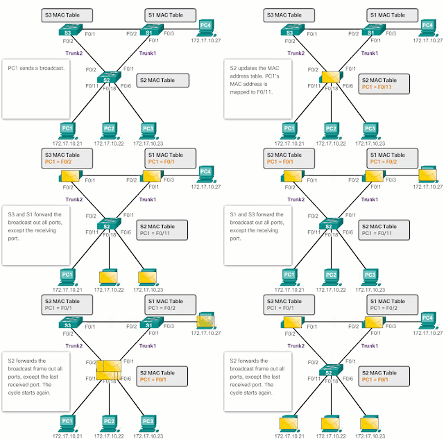
According to Image 2 :

  1. PC1 sends a broadcast frame to S2. S2 receives the broadcast frame in F0 / 11. When S2 receives the broadcast frame, it updates its MAC address table to record that PC1 is available on port F0 / 11.
  2. Because it is a broadcast frame, the S2 forwards the frame through all ports, including the Local_Link1 and the Local_Link2. When the broadcast frame reaches S3 and S1, they update their MAC address tables to indicate that PC1 is available on port F0 / 1 of S1 and on port F0 / 2 of S3.
  3. Since it is a broadcast frame, S3 and S1 forward the frame through all ports, except the input port. S3 sends broadcast frames from PC1 to S1. S1 sends broadcast frames from PC1 to S3. Each switch updates its MAC address table with the wrong port for PC1.
  4. Each switch resends the broadcast frame over all its ports, except the input port, which causes the two switches to forward the frame to S2.
  5. When S2 receives the broadcast frames of S3 and S1, the MAC address table is updated again, this time with the last input received from the other two switches.

This process is repeated again and again until the loop is broken by physically disconnecting the connections that cause it or by turning off one of the switches in the loop.

 Problem: Broadcast Storms

A broadcast storm occurs when there are so many broadcast frames trapped in a Layer 2 loop, that all available bandwidth is consumed . As a consequence, there is no bandwidth available for legitimate traffic and the network is no longer available for data communication. This is an effective denial of service.

Broadcast storm is inevitable in a network with loops. As more devices send broadcasts over the network, more traffic is concentrated in the loop, which consumes resources. Finally, a diffusion storm is created that causes the network to fail.
There are other consequences of broadcast storms, for example, it may cause the terminal to not work well because of the high processing requirements to maintain such a high traffic load in the NIC.

Detail of the problem with diffusion storms

According to Image 3 :


  1. PC1 sends a broadcast frame to the network with loops.
  2. The broadcast frame creates a loop between all interconnected switches in the network.
  3. PC4 also sends a broadcast frame to the network with loops.
  4. The broadcast frame of PC4 is also trapped in the loop between all interconnected switches, as is the broadcast frame of PC1.
  5. As more devices send broadcasts over the network, more traffic is concentrated in the loop, which consumes resources. Finally, a diffusion storm is created that causes the network to fail.
  6. When the network is completely saturated with broadcast traffic that generates a loop between the switches, the switch discards new traffic because it cannot process it.

Since devices connected to a network regularly send broadcast frames, such as ARP requests, a broadcast storm may form in seconds . As a result, when a loop is created, the switched network is quickly deactivated.

 Problem: Duplicate Unicast Frames

Broadcast frames are not the only type of frames that are affected by loops. Unicast frames sent to a network with loops can generate duplicate frames that reach the destination device.

Most upper layer protocols are not designed to recognize duplicate transmissions or deal with them. In general, protocols that use a sequence numbering mechanism assume that the transmission has failed and that the sequence number has been recycled for another communication session. Other protocols attempt to send the duplicate transmission to the appropriate upper layer protocol to be processed and possibly discarded.

Layer 2 LAN protocols, such as Ethernet, lack mechanisms to recognize and eliminate frames that form incessant loops . Some layer 3 protocols implement a TTL mechanism that limits the number of times a layer 3 network device can transmit a packet again. Layer 2 devices, which lack this mechanism, continue to relay the traffic that generates loops indefinitely. STP , a mechanism that serves to prevent loops in layer 2, was developed to address these problems.
To prevent these problems from occurring in a redundant network, some kind of expansion tree must be enabled on the switches . By default, the expansion tree is enabled on Cisco switches to prevent loops in Layer 2.

 Detail of the problem with diffusion storms

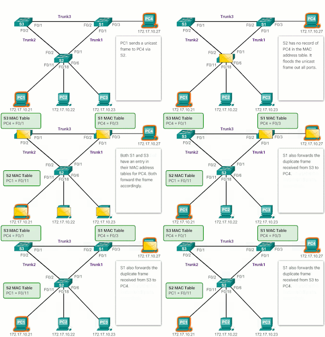
According to Image 4 :

  1. PC1 sends an unicast frame to PC4.
  2. The S2 does not have any input for PC4 in its MAC table, so it saturates all the ports of the switch with the unicast frame to try to find PC4.
  3. The frame reaches switches S1 and S3.
  4. S1 does not have a MAC address entry for PC4, so it resends the frame to PC4.
  5. S3 also has an entry in its MAC address table for PC4, so that it forwards the unicast frame through Trunk Link3 to S1.
  6. S1 receives the duplicate frame and forwards it to PC4.
  7. PC4 has now received the same frame twice.

Friday, 25 October 2019

Network Scaling : how to grow your Network Expansion

Network Scaling : how to grow your Network Expansion

Network Scalling is a very important concept in network design. A well-designed network controls traffic and limits the size of fault domains. A network design must include an IP addressing strategy, scalable and fast convergence routing protocols, appropriate layer 2 protocols and modular or clustered devices that can be easily updated to increase capacity. (how to grow your Network Expansion)
To support an enterprise network, the network designer must develop a strategy that allows the network to be available and can be scaled easily and efficiently .

Table of Contents

  • Design that supports scalability
  • Advanced network design requirements
  • LAN redundancy
  • Increase bandwidth
  • Expansion of the access layer
  • Adjust routing protocols
    • OSPF
    • EIGRP

Design that supports Scalability

In a basic network design strategy, the following recommendations are included:

  • Use expandable modular equipment or grouped devices that can be easily upgraded to increase capacities. Device modules can be added to existing equipment to support new devices and features without the need for large-scale equipment updates. Some devices can be integrated into a cluster to function as a single device, to simplify administration and configuration.
  • Design the hierarchical network to include modules that can be added, updated and modified as necessary, without affecting the design of other functional areas of the network. For example, create a separate access layer that can be expanded without affecting the distribution and core layers of the campus network.
  • Create an IPv4 or IPv6 address strategy that is hierarchical . If IPv4 addressing is meticulously planned, the need to redirect the network to support additional users and services is avoided.
  • Choose routers or multilayer switches to limit broadcast and filter other unwanted traffic on the network. Use Layer 3 devices to filter and reduce traffic to the network core.

Advanced network design requirements


As shown in Image 1, the most advanced network design requirements include the following:


  • The implementation of redundant links in the network , between the essential devices and the access layer and core layer devices.
  • The implementation of several links between the teams , either with link aggregation ( EtherChannel ) or with load balancing of the same cost to increase bandwidth. The combination of several Ethernet links in a single configuration with EtherChannel load balancing increases the available bandwidth. EtherChannel implementations can be used when, due to budget constraints, high-speed interfaces or fiber optic lines cannot be acquired.
  • The implementation of wireless connectivity to allow mobility and expansion.
  • The use of a scalable routing protocol and the implementation of features within that protocol to isolate routing updates and minimize the size of the routing table.

LAN Redundancy


For most organizations, network availability is critical to meet business needs. Redundancy is an important part of network design to prevent interruptions of network services by minimizing the possibility of a single point of failure. One method of implementing redundancy is to install duplicate equipment and provide failover services for essential devices.
Another method of implementing redundancy is through redundant routes. Redundant routes offer alternative physical routes for data to cross the network. In a switched network, redundant routes support high availability. However, due to the operation of the switches, redundant routes in a switched Ethernet network may cause logical loops in layer 2. For this reason, the tree expansion protocol ( STP ) is required.
The STP protocol allows the redundancy necessary to provide reliability, but eliminates switching loops. To do this, it provides a mechanism to disable redundant routes in a switched network until the route becomes necessary, for example, when a fault occurs. It is an open standards protocol, which is used in a switching environment to create a logical topology without loops.
In the next chapter "LAN redundancy", more details about LAN redundancy and STP operation are described.

Increase bandwidth

In the hierarchical network design, some links between access and distribution switches may need to process a greater amount of traffic than other links. As the traffic of several links converges on a single outbound link, a bottleneck may occur in that link .
Link aggregation allows the administrator to increase bandwidth between devices by creating a logical link composed of several physical links. As shown in Image 3, EtherChannel is a form of link aggregation that is used in switched networks.

EtherChannel uses the existing switch ports, therefore it is not necessary to incur additional costs to update the link to a faster and more expensive connection. The EtherChannel link looks like a logical link that uses an EtherChannel interface. Most configuration tasks are performed on the EtherChannel interface instead of on each individual port, which ensures configuration consistency across all links.
Finally, the EtherChannel configuration takes advantage of load balancing between the links that are part of the EtherChannel itself and, depending on the hardware platform, one or more load balancing methods can be implemented.

Expansion of the Access layer

The network should be designed to be able to expand network access for people and devices , as necessary. For the extension of access layer connectivity, wireless connectivity is increasingly important . The provision of wireless connectivity provides many advantages, such as increased flexibility, reduced costs and the ability to grow and adapt to the changing requirements of networks and businesses.

To communicate wirelessly, the terminals require a wireless NIC that incorporates a radio transmitter or receiver and the software driver necessary for it to work. As shown in Image 4, a wireless router or a wireless access point (AP) is also required for users to connect.

Adjust routing protocols

ISPs and business networks generally use more advanced routing protocols, such as link status protocols , due to their hierarchical design and the ability to scale to larger networks.

OSPF


Link state routing protocols, such as the OSPF (Open Shortest Path First) protocol , shown in Image 5, work well in larger hierarchical networks, where it is important to have rapid convergence. OSPF routers establish and maintain neighbor adjacencies with other OSPF routers connected.
When routers initiate an adjacency with neighbors, an exchange of Link-State updates begins . Routers reach a FULL adjacency state by synchronizing the views of their Link-State databases. With OSPF, Link-State updates are sent every time there are changes in the network.
OSPF is a popular link state routing protocol that can be adjusted in many ways. In the chapter “Setting and solving single area OSPF problems”, some of the more advanced features of OSPF configuration and troubleshooting are detailed.

In addition, OSPF supports a two-layer hierarchical design, or multi-area OSPF, shown in figure. All OSPF networks begin with an Area 0, also called a backbone area. As the network expands, other areas that are not backbone can be created. All non-backbone areas must be connected directly to area 0. In the chapter " Multi-area OSPF ", the benefits, operation and configuration of multi-area OSPF are presented.

 EIGRP

Another popular routing protocol in larger networks is the Enhanced Interior Gateway Routing Protocol (EIGRP). Cisco developed EIGRP as an exclusive vector distance routing protocol with enhanced capabilities. Although the EIGRP configuration is relatively simple, this protocol has broad and strong underlying features and options.

For example, EIGRP uses several tables, which are shown in above figure, to manage the routing process. EIGRP contains many functions that none of the other routing protocols have. It is an excellent choice for large multi-protocol networks in which Cisco devices are mainly used.
The "EIGRP" chapter describes the operation and configuration of the EIGRP routing protocol, while the chapter "Advanced configuration and troubleshooting of EIGRP" covers some of the most advanced EIGRP configuration options.

Network Design and Implementation

Network Design and Implementation

Article is on Strategies and methods used to systematically setup Network Design and Implementation, such as the hierarchical network design model and the Cisco enterprise architecture.
As a company grows, its network requirements also increase. Companies rely on network infrastructure to provide essential services. Network interruptions can cause profit and customer losses. Network designers must design and build a business network that is scalable and highly available .
Companies are increasingly turning to their network infrastructure to provide mission-critical services. As companies grow and evolve, they hire more employees, open branches and expand to global markets. These changes directly affect the network requirements. The network used to support the business activities of the company is called the business network .
A business network must support the exchange of various types of network traffic, including data files, email, IP telephony and video applications for various business units.
Table of Contents

  1. Commercial Devices for Companies
  2. Hierarchical Network Design
  3. Cisco Enterprise Architecture
  4. Failure domains

Commercial Devices For Companies

Users expect business networks, such as the one shown in Image 2, to be active 99.999% of the time. The interruptions that occur in business networks prevent companies from carrying out their normal activities, which can lead to loss of profits, customers, data and opportunities.
In order to reach this level of reliability, advanced technology equipment of enterprise class is usually installed in the business network. Business teams, designed and manufactured to meet stricter standards than cheaper devices, carry a large volume of network traffic.
High-tech equipment is designed to be reliable, with features such as redundant power supplies and migration capacity in case of failures. Failover capability is the ability of a device to move from a module, service or device that does not work to one that does without interrupting the service or with minimal interruption.

Hierarchical Network Design

To optimize bandwidth in an enterprise network, the network must be organized so that traffic is maintained at the local level and does not spread unnecessarily to other parts of the network. The use of the three-layer hierarchical design model helps to organize the network.
In above figure, in this model the functionality of the network is divided into three different layers.

  1. Access layer
  2. Distribution layer
  3. Core layer

Each layer is designed to fulfill specific functions.
The access layer provides connectivity to users. The distribution layer is used to send traffic from one local network to another. Finally, the core layer represents a high-speed backbone between the dispersed networks. User traffic starts at the access layer and passes through the other layers if you need to use the functionality of those layers.

Although the hierarchical model consists of three layers, a two-tier hierarchical design may be implemented in some small business networks. As shown in Image 4, in a two-tier hierarchical design , the core and distribution layers are combined into one, which reduces cost and complexity.

Cisco Enterprise Architecture

The Cisco enterprise architecture divides the network into functional components , while maintaining the core, distribution and access layers.

As shown in Image 5, the main modules of the Cisco enterprise architecture include the following:

  1. Business campus
  2. Business perimeter
  3. Perimeter of the service provider
  4. Remote

 Business campus

The business campus module is composed of all the campus infrastructure and includes the access, distribution and core layers.

  • The access layer module includes layer 2 or layer 3 switches to provide the required port density. In this module, the implementation of VLANs and trunk links to the building's distribution layer occurs. Redundancy to building distribution switches is important.
  • The distribution layer module adds access to the building through layer 3 devices. In the distribution layer module, routing, access control and QoS are carried out.
  • The core layer module provides high-speed inter connectivity between the distribution layer modules, the data center server farms and the business perimeter. In this module, the central axis of the design is redundancy, rapid convergence and fault tolerance.

In addition to these modules, the business campus may include other sub-modules, such as the following:
Data center and server farm module : this area provides high speed connectivity and protection for servers. It is very important to provide security, redundancy and fault tolerance.
Services module : this area provides access to all services, such as IP telephony services, wireless controller services and unified services.

Business perimeter

The business perimeter module is composed of the Internet, VPN and WAN modules that connect the company to the service provider's network. This module extends the company's services to remote sites and allows the company to use Internet and partner resources. Provides QoS, policy reinforcement, service levels and security.

Perimeter of the service provider

The perimeter module of the service provider provides Internet, public switched telephone network (PSTN) and WAN services .
The composite business network (ECNM) model passes through an end device. This is the moment in which the packages can be analyzed and the decision can be made as to whether they should be allowed to enter the business network. Intrusion detection systems (IDS) and intrusion prevention systems (IPS) can also be configured on the business perimeter to provide protection against malicious activities.

Failure domains

A well-designed network not only controls traffic, but also limits the size of fault domains . A fault domain is the area of ​​the network that is affected when an essential device or network service experiences problems.
The function of the device that initially fails determines the impact of the fault domain. For example, a switch that malfunctions in a network segment usually affects only the hosts in that segment. However, if the fault occurs in the router that connects this segment with other segments, the impact is much greater.
The use of redundant links and reliable high-tech equipment minimizes the chances of interruptions to network services. If the domains of failures are smaller, the impact of the failures on the productivity of the company is reduced. In addition, they simplify the problem-solving process, which reduces downtime for all users.

Limitation of fault domain size

Since a failure in the core layer of a network can have a great impact, the network designer often focuses on efforts to prevent failures. These efforts can lead to a large increase in the cost of network implementation. In the hierarchical design model, it is easier and generally more economical to control the size of a fault domain in the distribution layer. In this layer, network errors can be contained in a smaller area, so that fewer users are affected. When layer 3 devices are used in the distribution layer, each router functions as a gateway for a limited number of users in the access layer.

Implementation of a switch block

Routers, or multilayer switches, are generally implemented in pairs, and access layer switches are divided equally between them. This configuration is called " building switch block " or "department". Each block of switches works independently. As a result, the failure of a single device does not deactivate the network. Not even the failure of a whole block of switches affects a large number of end users.

Wednesday, 7 August 2019

Network Diagram or Network Representations | Topology Diagram

Network Diagram or Network Representations | Topology Diagram


To representing a network we use different symbol and topology icon, and this Topology Diagram known as Network Diagrams. In this section we will see the Logical Topology Diagrams and the Physical Topology Diagrams. The topology diagrams are mandatory for everyone working with networks. This is how a network is represented.

Network Symbols


Network diagrams use symbols / images to represent the different devices and connections that make up a network. A diagram allows you to easily understand the way in which devices are connected in a large network. This type of representation of a network is called a topology diagram . The ability to recognize the logical representations of physical network components is essential to visualize the organization and operation of a network.


In addition to these representations, specialized terminology is used when talking about how these devices and the media connect to each other. Some important terms to remember are:


  • Network interface card: A NIC, or LAN adapter, provides the physical connection to the network on the PC or other terminal. The means that connect the PC to the network device are connected directly to the NIC.
  • Physical port: a connector or connection on a network device where the media is connected to a terminal or other network device.
  • Interface: specialized ports on a network device that connects to individual networks. Since routers are used to interconnect networks, the ports of a router are known as network interfaces.

TYPES OF NETWORK DIAGRAMS

Topology diagrams are mandatory for everyone who works with networks. These diagrams provide a visual map that shows how the network is connected.

There are two types of topology diagrams:

PHYSICAL TOPOLOGY DIAGRAM

Identify the physical location of the intermediary devices and the installation of the cables.


LOGIC TOPOLOGY DIAGRAM

Identify devices, ports and addressing scheme.

In summary, the topologies shown in the physical and logical diagrams are appropriate for your level of understanding at this point in the course.