Showing posts with label cisco ACL. Show all posts

Sunday, 27 October 2019

EtherChannel Link Aggregation Configuration on Cisco Router

EtherChannel Link Aggregation Configuration on Cisco Router 

This is detailed article on EtherChannel Link Aggregation Configuration on Cisco Router, as well as the verification and troubleshooting of link aggregation with EtherChannel.

EtherChannel Configuration on Cisco


The following guidelines and restrictions are useful for configuring EtherChannel:

  • EtherChannel support : all Ethernet interfaces on all modules must support EtherChannel, without the need for the interfaces to be physically contiguous or on the same module.
  • Speed ​​and duplex : Configure all interfaces in an EtherChannel to operate at the same speed and in the same duplex mode, as shown in the illustration.
  • VLAN Matching : All interfaces in the EtherChannel group must be assigned to the same VLAN or configured as a trunk, which is also shown in the illustration.
  • VLAN Range : An EtherChannel supports the same allowed VLAN range on all interfaces of a
  • EtherChannel trunk. If the allowed VLAN range is not the same, the interfaces do not form an EtherChannel, even if they are set to automatic or desired mode.
If these parameters must be modified, configure them in the port channel interface configuration mode.
After configuring the port channel interface, any configuration that applies to this interface also affects the individual interfaces. However, the settings that apply to individual interfaces do not affect the port channel interface. Therefore, making configuration changes to an interface that is part of an EtherChannel link can cause interface compatibility problems .

Interface configuration

The configuration of EtherChannel with LACP is done in two steps:

  • Step 1 . Specify the interfaces that make up the EtherChannel group using the interface range range interface command in global configuration mode. The range keyword allows you to select several interfaces and configure them at the same time. It is recommended to start by deactivating those interfaces, so that no incomplete configuration creates link activity.
  • Step 2 . Create the port channel interface with the channel-group identifier mode active command in interface range configuration mode. The identifier specifies the channel group number. Mode active keywords identify this setting as EtherChannel LACP.

In Image 2, FastEthernet0 / 1 and FastEthernet0 / 2 are grouped in the EtherChannel 1 interface port channel.


To change the Layer 2 configuration in the port channel interface, enter the port channel interface configuration mode using the interface port-channel command , followed by the interface identifier.
In the example, the EtherChannel is configured as a trunk link interface with specific allowed VLANs. In Image 2, it is also shown that the interface port channel 1 is configured as a trunk link with the allowed VLANs 1, 2 and 20.

EtherChannel Verification

There are a variety of commands to verify an EtherChannel configuration .

  • First, the show interface port-channel command shows the general status of the port channel interface. In Image 3, the port channel interface 1 is active.


  • When multiple port channel interfaces are configured on the same device, use the show etherchannel summary command to display a single line of information per port channel. In Image 4, the switch has an EtherChannel configured; Group 1 uses LACP.

The interface group consists of the FastEthernet0 / 1 and FastEthernet0 / 2 interfaces. The group is a Layer 2 EtherChannel and is in use, as indicated by the letters SU next to the port channel number.


  • Use the show etherchannel port-channel command to display information about a specific port channel interface, as shown in Image 5.

In the example, the port channel interface 1 consists of two physical interfaces, FastEthernet0 / 1 and FastEthernet0 / 2. It uses LACP in active mode. It is correctly connected to another switch with a compatible configuration, which is why it is said that the port channel is in use.
In any member of a physical interface of an EtherChannel group, the show interfaces etherchannel command can provide information about the function of the interface in the EtherChannel, as shown in following figure.

The FastEthernet0 / 1 interface is part of the EtherChannel 1 group. The protocol for this EtherChannel is LACP.

EtherChannel troubleshooting

All interfaces within an EtherChannel must have the same speed and duplex mode settings, native and allowed VLANs on trunk links, and access VLANs on access ports.

  • Assign all ports on the EtherChannel to the same VLAN or configure them as a trunk. Ports with different native VLANs cannot form an EtherChannel.
  • When configuring an EtherChannel from trunk links, verify that the trunk mode is the same on all trunk links . Inconsistent trunk link modes on the EtherChannel ports can cause EtherChannel to not work and the ports to be disabled (errdisable state).
  • An EtherChannel supports the same allowed VLAN range on all ports . If the allowed VLAN range is not the same, the ports do not form an EtherChannel, even when PAgP is set to automatic or desirable mode.
  • Dynamic negotiation options for PAgP and LACP must be configured in a compatible manner at both ends of the EtherChannel.

Note : it is easy to confuse PAgP or LACP with DTP, since both are protocols that are used to automate the behavior on trunks. PAgP and LACP are used for link aggregation (EtherChannel). DTP is used to automate the creation of trunks. When an EtherChannel trunk is configured, EtherChannel (PAgP or LACP) is usually configured first and then DTP.

Result Examples

In Image 7, the F0 / 1 and F0 / 2 interfaces on switches S1 and S2 are connected to an EtherChannel. The result indicates that the EtherChannel is inactive.

In Image 8, a more detailed result indicates that there are incompatible PAgP modes configured on switches S1 and S2.
EtherChannel 2 troubleshooting
Image 8: incompatible PAgP modes

In Image 9, the PAgP mode in the EtherChannel is changed to desired, and the EtherChannel is activated.

If you try to change the configuration directly, the errors in the expansion tree cause the associated ports to enter the blocking or errdisabled state .

Friday, 18 October 2019

Access Control List ACL Configuration on Cisco Router

Access Control List ACL Configuration on Cisco Router

It explains Access Control List ACL Configuration on Cisco Router. If you want to learn what is Access Control List, you can visit the previous post.
To use standard ACLs numbered on a Cisco router, you must first create the standard ACL and then activate it on an interface.
The global access-list  configuration command  defines a standard ACL with a number between 1 and 99. Version 12.0.1 of the Cisco IOS software extended that range and allows numbers ranging from 1300 to 1999 to be used for standard ACLs . This allows a maximum of 798 possible standard ACLs to be generated. These additional numbers are called extended IPv4 ACLs.
List of Contents For ACL Configuration
1. Commands to configure ACL
2. Modify IPL4 ACL
3. VTY Port Protection with Standard IPv4 ACL

Commands to configure ACL

For ACL you can configure standard ACL on Cisco Router using the following commands syntax:
Router (config) # access-list access-list-number {deny | permit | remark} source [source-wildcard] [log]
In the following table, the syntax for a standard ACL is explained in detail.
Parameter
Description
access list number
Number of an ACL. It is a decimal number from 1 to 99 or from 1300 to 1999 (for standard ACLs).
deny
Deny access if conditions match.
allow
Allow access if conditions match.
remark
Add a comment about the entries in the IP access list to facilitate the understanding and analysis of the list.
origin
Network or host number from which the packet is sent. There are two ways to specify the origin.
Use a 32-bit quantity in dotted decimal format of four parts.
Use the keyword any as the source abbreviation and source wildcard of 0.0.0.0 255.255.255.255.
source wildcard
(Optional) 32-bit wildcard mask to apply to the source. Place some in the bit positions that you want to skip.
Standard ACL command syntax table access-list
ACEs can allow or deny a single host or a range of host addresses. To create a host instruction in ACL numbered 10 that allows a specific host with IPv4 address 192.168.10.10, you must enter the following:
R1 (config) # access-list 10 permit host 192.168.10.10

ACL REMOVAL

To create an instruction that allows a range of IPv4 addresses in an ACL numbered 10 that allows all IPv4 addresses on the 192.168.10.0/24 network, you must enter the following:
R1 (config) # access-list 10 permit 192.168.10.0 0.0.0.255
To remove the ACL, the global no access-list configuration command is used. Executing the show access-list command confirms that the access list 10 was deleted.

R1 # show access-lists
Standard IP access list 10
 10 permit 192.168.10.0, wildcard bits 0.0.0.255
R1 # conf t
Enter configuration commands, one per line. End with CNTL / Z.
R1 (config) # no access-list 10
R1 (config) # exit
R1 # show access-lists
R1 #

Usually, when an administrator creates an ACL, he knows and understands the purpose of each instruction. However, to ensure that the administrator and others remember the purpose of the instructions, comments (remarks) must be included. The remark keyword is used in documents and makes it much easier to understand access lists. The text of each comment has a limit of 100 characters. The ACL shown below, which is quite simple, is used as an example. When the ACL in the configuration is checked using the show running-config command, the comment is also displayed.

R1 (config) # access-list 10 remark Permit hosts from the 192.168.10.0 LAN 
R1 (config) # access-list 10 permit 192.168.10.0 0.0.0.255 
R1 (config) # exit 
R1 # show running-config | include access-list 10 
access-list 10 remark Permit hosts from the 192.168.10.0 LAN 
access-list 10 permit 192.168.10.0 0.0.0.255 
R1 #

APPLICATION OF STANDARD IPV4 ACLS TO INTERFACES

After a standard IPv4 ACL is configured, it is linked to an interface using the ip access-group command in interface configuration mode:
Router (config-if) # ip access-group {access-list-number | access-list-name} {in | out
To remove an ACL from an interface, first enter the  no ip access-group  command in the interface, and then enter the global no access-list command   to remove the entire ACL.
The steps and syntax for configuring and applying a standard numbered ACL on a router are listed below.

1 : Use the global access-list configuration command  to create an entry in a standard IPv4 ACL.
R1 (config) # access-list 1 permit 192.168.10.0 0.0.0.255
2 : Use the interface configuration command to select an interface to which to apply the ACL.
R1 (config) # interface serial 0/0/0
3 : Use the ip access-group interface configuration command to activate the current ACL on an interface.
R1 (config-if) # ip access-group 1 out

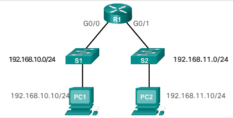
EXAMPLE OF AN ACL DESIGNED TO ALLOW A SINGLE NETWORK.


This ACL only allows traffic from the source network 192.168.10.0 to be forwarded via the S0 / 0/0 interface. Traffic from networks other than the 192.168.10.0 network is blocked.
R1 (config) # access-list 1 permit 192.168.10.0 0.0.0.255
R1 (config) # interface s0 / 0/0
R1 (config-if) # ip access-group 1 out
On the first line, the ACL is identified as an access list 1. This list allows traffic that matches the selected parameters. In this case, the IPv4 address and wildcard mask that identify the source network are 192.168.10.0 0.0.0.255. Remember that there is an implicit denial of all instructions that are equivalent to adding the  access-list line 1 deny 0.0.0.0 255.255.255.255  or  access-list deny any  at the end of the ACL.
The ip access-group 1 out interface configuration command   links ACL 1 to Serial 0/0/0 as an output filter.
Therefore, ACL 1 only allows hosts on the 192.168.10.0/24 network to exit router R1. This list denies any other network, including the 192.168.11.0 network

EXAMPLES OF STANDARD ACLS NUMBERED IPV4

Continuing with the example of the previous image, let's look at the following commands: (Denial of a specific host and admission of a specific subnet)
R1 (config) # no access-list 1
R1 (config) # access-list 1 deny host 192.168.10.10
R1 (config) # access-list 1 permit 192.168.10.0 0.0.0.255
R1 (config) # interface s0 / 0/0
R1 (config-if) # ip access-group 1 out
The first command removes the previous version of ACL 1. The following ACL instruction denies the host of PC1 located at 192.168.10.10. All other hosts in the 192.168.10.0/24 network are then allowed. In this case, the implicit deny statement also matches all other networks.
The ACL is reapplied to the S0 / 0/0 interface in the output direction.
Now we show an example of an ACL that denies a specific host. This ACL replaces the previous example. In this example, host traffic PC1 is still blocked, but the rest of the traffic is allowed.
R1 (config) # no access-list 1
R1 (config) # access-list 1 deny host 192.168.10.10 
R1 (config) # access-list 1 allow any
R1 (config) # interface g0 / 0
R1 (config-if) # ip access-group 1 in
The first two commands are the same as in the previous example. The first command removes the previous version of ACL 1, and the following ACL instruction denies host PC1 that is located at 192.168.10.10.
The third line is new and allows the rest of the hosts. This means that all hosts on the 192.168.10.0/24 network are allowed, except PC1, which was denied in the previous instruction.
This ACL is applied to the G0 / 0 interface in the input direction. Because the filter affects only the 192.168.10.0/24 LAN in G0 / 0, it is more efficient to apply the ACL to the input interface. The ACL can be applied to S0 / 0/0 in the outbound direction, but then R1 would have to examine the packets of all networks, including 192.168.11.0/24.

ACL SYNTAX WITH IPV4 STANDARD NAME

Naming ACLs makes it easier to understand their function. When the ACL is identified with a name instead of a number, the configuration mode and command syntax are subtly different.
Below are the steps necessary to create a standard named ACL.

  • Step 1:  In global configuration mode, use the ip access-list command   to create a named ACL. ACL names are alphanumeric, are case sensitive and must be unique. The ip access-list standard name command   is used to create one with a standard name. After entering the command, the router is in standard configuration mode (std) ACL with name (nacl) as indicated by the second indicator in:
Router (config) # ip access-list [ standard | extended ] name
Router (config-std-nacl) # [ permit | deny | remark ] {source [ source-wildcard ]} [ log ]
Note : Numbered ACLs use the global access-list configuration command, while named IPv4 ACLs use the ip access-list command.
  • Step 2:  In the named ACL configuration mode, use the permit  or  deny instructions   to specify one or more conditions to determine if a packet is forwarded or discarded. You can use  remark  to add a comment to the ACL.
  • Step 3:  Apply the ACL to an interface with the command  ip access-group  name . Specify whether the ACL should be applied to packets when they enter through the interface (in) or when they exit the interface (out).
Router (config-if) # ip access-group  name [ in | out ]
The following are the commands used to configure a standard ACL with name on router R1, in which the G0 / 0 interface denies host 192.168.11.10 access to the 192.168.10.0 network. The ACL is called NO_ACCESS.
R1 (config) # ip access-list standard NO_ACCESS
R1 (config-std-nacl) # deny host 192.168.11.10
R1 (config-std-nacl) # permit any
R1 (config-std-nacl) # exit
R1 (config) # interface g0 / 0
R1 (config-if) # ip access-group NO_ACCESS out
It is not necessary for ACL names to begin with a capital letter, but this makes them stand out when the result of show running-config is observed. It also makes it less likely that you accidentally create two different ACLs with the same name but with different capitalization.

MODIFY IPL4 ACL

After familiarizing yourself with the process of creating and editing ACLs, it may be easier to generate the ACL using a text editor such as Microsoft Notepad. This allows you to create or edit the ACL and then paste it into the router interface. For an existing ACL, you can use the show running-config command   to display the ACL, copy and paste it into the text editor, make the necessary changes and paste it back into the router interface.
Setting.  Assume, for example, that the following IPv4 host address was entered incorrectly. Instead of host 192.168.10.99, it should be host 192.168.10.10. The steps to edit and correct ACL 1 are as follows:
R1 (config) # access-list 1 deny host 192.168.10.99
R1 (config) # access-list 1 permit 192.168.0.0 0.0.255.255
  • Step 1:  Display the ACL using the show running-config command  . In the example in the illustration, the include  keyword is used  to show only ACEs.
R1 # show running-config | include access-list 1
 access-list 1 deny host 192.168.10.99
access-list 1 permit 192.168.0.0 0.0.255.255

  • Step 2:  Select the ACL, copy it, and then paste it into Microsoft Notepad. Edit the list as necessary. Once the ACL is displayed correctly in Microsoft Notepad, select it and copy it.
<Text editor>
access-list 1 deny host 192.168.10.10
access-list 1 permit 192.168.0.0 0.0.255.255

  • Step 3:  In global configuration mode, delete the access list with the no access-list 1 command  . Otherwise, the new instructions will be added to the existing ACL. Next, paste the new ACL into the router configuration.
R1 # config t
Enter configuration commands, one per line. End with CNTL / Z.
R1 (config) # no access-list 1
R1 (config) # access-list 1 deny host 192.168.10.10
R1 (config) # access-list 1 permit 192.168.0.0 0.0.255.255
  • Step 4:  Verify changes using the show running-config command  .
R1 # show running-config | include access-list 1
 access-list 1 deny host 192.168.10.10 
access-list 1 permit 192.168.0.0 0.0.255.255
It is necessary to remember that, when using the no access-list command  , the different versions of the IOS software act differently. If the ACL that was removed is still applied to an interface, some versions of the IOS act as if there is no ACL that protects the network, while others deny all traffic. For this reason, it is advisable to remove the reference to the access list of the interface before modifying the list . If there is an error in the new list, you must disable it and solve the problem. In that case, the network has no ACL during the correction process.

METHOD 2: USE SEQUENCE NUMBERS

R1 (config) # access-list 1 deny host 192.168.10.99
R1 (config) # access-list 1 permit 192.168.0.0 0.0.255.255
As shown in the scheme above, a host instruction for host 192.168.10.99 was included in the initial configuration of ACL 1. But that was a mistake. Host 192.168.10.10 should have been configured. To edit the ACL with sequence numbers, follow these steps:
  • Step 1:  Display the current ACL using the show access-lists 1 command  . The result of this command will be analyzed in more detail later in this section. The sequence number is shown at the beginning of each instruction. The sequence number was automatically assigned when the access list instruction was entered. Note that the instruction that is incorrectly configured has sequence number 10.
R1 # show access-lists 1
Standard IP access list 1
 10 deny 192.168.10.99
 20 permit 192.168.0.0, wildcard bits 0.0.255.255
R1 #
  • Step 2:  Enter the ip access-lists standard command   that is used to configure named ACLs. The ACL number, 1, is used as a name. First, the misconfigured instruction must be removed with command  no 10 , where "10" refers to the sequence number. Then, a new sequence number instruction 10 is added by command  10 deny host 192.168.10.10 .
R1 # conf t 
R1 (config) # ip access-list standard 1
R1 (config-std-nacl) # no 10
R1 (config-std-nacl) # 10 deny host 192.168.10.10
R1 (config-std-nacl) # end
R1 #
Note:  Instructions cannot be overwritten with the same sequence number as an existing instruction. First, the current instruction must be deleted and then the new one can be added.

  • Step 3:  Verify the changes using the show access-lists command  .
R1 # show access-lists
Standard IP access list 1
 10 deny 192.168.10.10
 20 permit 192.168.0.0, wildcard bits 0.0.255.255
R1 #
As mentioned earlier, Cisco IOS implements internal logic in standard access lists. It is possible that the order in which standard ACEs are introduced is not the order in which they are stored, displayed or processed on the router. The show access-lists command   shows ACEs with their sequence numbers.

STANDARD ACL EDITION WITH NAME

In an earlier example, sequence numbers were used to edit a standard ACL numbered IPv4. By reference to the sequence numbers of the instruction, individual instructions can be easily inserted or deleted. This method can also be used to edit standard named ACLs.
In the following scheme, an example of inserting a line in a named ACL is shown.
R1 # show access-lists
Standard IP access list NO_ACCESS
 10 deny 192.168.11.10
 20 permit 192.168.11.0, wildcard bits 0.0.0.255
R1 # conf t
Enter configuration commands, one per line. End with CNTL / Z.
R1 (config) # ip access-list standard NO_ACCESS
R1 (config-std-nacl) # 15 deny host 192.168.11.11
R1 (config-std-nacl) # end
R1 # show access-lists
Standard IP access list NO_ACCESS
 10 deny 192.168.11.10
 15 deny 192.168.11.11
 20 permit 192.168.11.0, wildcard bits 0.0.0.255
R1 #
In the first result of the show command  , you can see that the ACL with the name NO_ACCESS has two numbered lines that indicate the access rules for a workstation with the IPv4 address 192.168.11.10.
Instructions can be inserted or deleted from the named access list configuration mode.
To add an instruction to deny another workstation, a numbered line must be inserted. In the example, the workstation with the IPv4 address 192.168.11.11 is added using the new sequence number 15.
Using the last result of the show command  , it is verified that the new workstation now has access denied.
Note : In the named access list configuration mode, enter the no  sequence-number command   to quickly remove individual instructions.

VERIFY Access Control List on Cisco

As shown below, the show ip interface command is used to verify the ACL on the interface. The result of this command includes the number or name of the access list and the direction in which the ACL was applied. The result shows that access list 1 is applied to the output interface S0 / 0/0 of router R1 and that the access list NO_ACCESS is applied to interface g0 / 0, also in the output direction.
R1 # show ip interface s0 / 0/0
Serial0 / 0/0 is up, line protocol is up
 Internet address is 10.1.1.1/30
<The result was omitted>
Outgoing access list is 1
Inbound access list is not set
<The result was omitted>
R1 # show ip interface g0 / 0
GigabitEthernet0 / 0 is up, line protocol is up
 Internet address is 192.168.10.1/24
<The result was omitted>
 Outgoing access list is NO_ACCESS
 Inbound access list is not set
<The result was omitted>
The result of issuing the show access-lists command   on router R1 is shown below. To view an individual access list, use the show access-lists command   followed by the number or name of the access list. The NO_ACCESS instructions may look strange. Note that sequence number 15 is shown before sequence number 10. This is due to the router's internal process and will be discussed later in this section.
R1 # show access-lists
Standard IP access list 1
 10 deny 192.168.10.10
 20 permit 192.168.0.0, wildcard bits 0.0.255.255
Standard IP access list NO_ACCESS
 15 deny 192.168.11.11
 10 deny 192.168.11.10
 20 permit 192.168.11.0, wildcard bits 0.0.0.255
R1 #

Access Control List STATISTICS

Once the ACL was applied to an interface and some tests were performed, the show access-lists command shows the statistics for each instruction that has matches. In the result shown below, notice that matches were found for some of the instructions.
R1 # show access-lists
Standard IP access list 1
 10 deny 192.168.10.10 (4 match (s))
 20 permit 192.168.0.0, wildcard bits 0.0.255.255
Standard IP access list NO_ACCESS
 15 deny 192.168.11.11
 10 deny 192.168.11.10 (4 match (s))
 20 permit 192.168.11.0, wildcard bits 0.0.0.255
R1 #
When traffic is generated that must match an ACL instruction, the matches shown in the result of the show access-lists  command  should increase. For example, in this case, if you ping from PC1 to PC3 or PC4, the result will show an increase in matches for the deny instruction of ACL 1.
R1 # show access-lists
Standard IP access list 1
10 deny 192.168.10.10 (8 match (s))
20 permit 192.168.0.0, wildcard bits 0.0.255.255
Standard IP access list NO_ACCESS
15 deny 192.168.11.11
10 deny 192.168.11.10 (4 match (s))
20 permit 192.168.11.0, wildcard bits 0.0.0.255
R1 #
Both permit and deny instructions keep track of match statistics; however, remember that each ACL has an implicit deny any instruction as the last instruction. This instruction does not appear in the show access-lists command, so no statistics are displayed for that instruction. To see the statistics of the implicit deny any instruction, the instruction can be configured manually and will appear in the result.
During the test of an ACL, the counters can be cleared using the clear access-list counters command  . This command can be used alone or with the number or name of a specific ACL. As shown below, this command clears the statistics counters for an ACL.
R1 # show access-lists
Standard IP access list 1
10 deny 192.168.10.10 (4 match (s))
20 permit 192.168.0.0, wildcard bits 0.0.255.255
Standard IP access list NO_ACCESS
15 deny 192.168.11.11
10 deny 192.168.11.10 (4 match (s))
20 permit 192.168.11.0, wildcard bits 0.0.0.255
R1 # clear access-list counters 1
R1 #
R1 # show access-lists
Standard IP access list 1
10 deny 192.168.10.10
20 permit 192.168.0.0, wildcard bits 0.0.255.255
Standard IP access list NO_ACCESS
15 deny 192.168.11.11
10 deny 192.168.11.10 (4 match (s))
20 permit 192.168.11.0, wildcard bits 0.0.0.255

VTY Port Protection with Standard IPv4 ACL

You can improve the security of administrative lines by restricting access to VTY. VTY access restriction is a technique that allows you to define the IP addresses that are allowed to remotely access the router's EXEC process. You can control which IP addresses can access the router remotely by configuring an ACL and an access-class instruction on VTY lines. Use this technique with SSH to further improve administrative access security.
The access-class command   configured in the line configuration mode restricts the input and output connections between a given VTY (on a Cisco device) and the addresses in an access list.
The syntax of the access-class command   is as follows:
Router (config) #  access-class  acl-number  {  in  [  vrf-also  ] |  out }
The in parameter   limits the input connections between the addresses in the access list and the Cisco device, while the out parameter   limits the output connections between a particular Cisco device and the addresses in the access list.
In Image 2, an example is shown in which a range of addresses is allowed to access the VTY lines from 0 to 4. The ACL in the illustration was configured to allow the 192.168.10.0 network to access the VTY lines of 0 to 4, but to deny the other networks.
To configure access lists in VTY, the following must be taken into account:
  • Numbered and named access lists can be applied to VTYs.
  • Identical restrictions must be established on all VTYs, because a user can try to connect to any of them.
R1 (config) # line vty 0 4
R1 (config-line) # local login
R1 (config-line) # transport input ssh
R1 (config-line) # access-class 21 in
R1 (config-line) # exit
R1 (config) # access-list 21 permit 192.168.10.0 0.0.0.255
R1 (config) # access-list 21 deny any
Note : Access lists apply to packets that are transported through a router, they are not designed to block packets that originate from the router. By default, outbound ACLs do not prevent remote access connections that are initiated from the router.

VTY PORT SECURITY VERIFICATION

After configuring the ACL to restrict access to VTY lines, it is important to verify that it works correctly. The following illustration shows two devices that try to connect to R1 via SSH. Access list 21 was configured on VTY lines on R1. PC1 manages to connect, while PC2 cannot establish an SSH connection. This is the expected behavior, since the configured access list allows access to VTY from the 192.168.10.0/24 network and denies the rest of the devices.

PC1> ssh 192.168.10.1
Login as: admin
Password: *****
R1>
PC2> ssh 192.168.11.1
ssh connect to host 192.168.11.1 port 
22: Connection refused
PC2>
The result of R1 shows what is produced by issuing the show access-lists  command  after PC1 and PC2 attempt to connect using SSH.
R1 # show access-lists
Standard IP access list 21
 10 permit 192.168.10.0, wildcard bits 0.0.0.255 (2 matches)
 20 deny any (1 match)
R1 #
The coincidence in the permit line of the result is the product of a correct SSH connection of PC1. The match in the deny statement is due to the failed attempt of PC2, a device in the 192.168.11.0/24 network, to establish an SSH connection.

Thursday, 17 October 2019

Access Control List Cisco | ACL Rules

Access Control List Cisco ACL Rules

Here you will learn the purpose & guidelines for the creation & placement of Access Control List Cisco in order to provide security to a network are explained . In the last part of post you will see Cisco ACL Rules.
One of the most important skills a network administrator needs is the domain of access control lists (ACLs). Network designers use firewalls to protect networks from unauthorized use. Firewalls are hardware or software solutions that enforce network security policies and filter unauthorized or potentially dangerous packets and prevent them from entering the network. On a Cisco router , you can configure a simple firewall that provides basic traffic filtering capabilities through ACL . Administrators use ACLs to stop traffic or to allow only specific traffic on their networks.
Contents of this Article
1. What is the access control list?
2. Filtering packages
3. Operation of the ACLs
4. Wildcard masks in ACL
5. Guidelines for the creation of ACL
6. Guidelines for the placement of ACL

What is the access control list Cisco?

An ACL is a series of IOS commands that control whether a router forwards or discards packets based on the information found in the packet header. ACLs are one of the most used features of Cisco IOS software.

ACL TASKS

When configured, ACLs perform the following tasks:
  • They limit network traffic to increase their performance . For example, if corporate policy does not allow video traffic on the network, ACLs that block video traffic can be configured and applied. This would significantly reduce the network load and increase its performance.
  • They provide traffic flow control . ACLs can restrict the delivery of routing updates to ensure that the updates come from a known source.
  • They provide a basic level of security for network access . ACLs can allow one host to access a part of the network and prevent another host from accessing the same area.
  • They filter the traffic according to the type of traffic . For example, an ACL can allow email traffic, but block all Telnet traffic.
  • They filter hosts to allow or deny them access to network services . ACLs can allow or deny users access to certain types of files, such as FTP or HTTP.
Routers do not have ACLs configured by default, so they do not filter traffic by default. The traffic that enters the router is routed only based on the information in the routing table. However, when an ACL is applied to an interface, the router performs the additional task of evaluating all network packets as they pass through the interface to determine if the packet can be forwarded.

FILTERING PACKAGES

An ACL is a sequential list of permit (allow) or deny (deny) instructions , known as “ access control entries ” (ACE). ACEs are also commonly referred to as "ACL instructions." When the network traffic crosses an interface configured with an ACL, the router compares the information within the packet with each ACE, in sequential order, to determine if the packet matches one of the ACEs. This process is called packet filtering .
Packet filtering controls access to a network by analyzing incoming and outgoing packets and transferring or discarding these according to certain criteria. Packet filtering can occur in layer 3 or layer 4.
Standard ACLs filter only in Layer 3. Extended ACLs filter in layers 3 and 4.
The filtering criteria established in each ACE of a standard IPv4 ACL is the source IPv4 address. A router configured with a standard IPv4 ACL retrieves the source IPv4 address of the packet header. The router starts at the top of the ACL and compares the address with each ACE sequentially. When it finds a match, the router performs the instruction, which may be to allow or deny the packet. Once a match is found, the remaining ACEs of the ACL, if any, are not analyzed. If the source IPv4 address does not match any ACE in the ACL, the packet is discarded.
The last instruction of an ACL is always an implicit denial. This statement is automatically inserted at the end of each ACL, even if it is not physically present. Implicit denial blocks all traffic. Due to this implicit denial, an ACL that does not have at least one permit instruction will block all traffic .

Operation of the ACLs

Access Control Lists define the set of rules that provide additional control for packets that enter through the input interfaces, for those that relay through the router, and for those that exit through the router's output interfaces. ACLs do not operate on packets that originate from the router itself.

  •  Inbound ACL: Incoming packets are processed before routing to the outgoing interface. Inbound ACLs are effective, because they save the overhead of routing searches if the packet is dropped. If ACLs allow the packet, it is processed for routing. The input ACLs are ideal for filtering packets when the network connected to an input interface is the only source of the packets to be examined.
  • Outbound ACL:  Inbound packets are routed to the outbound interface and then processed through the outbound ACL. Output ACLs are ideal when the same filter is applied to packets that come from several input interfaces before leaving through the same output interface

Wildcard masks in ACL

IPv4 ACEs include the use of wildcard masks. A wildcard mask is a 32-bit binary string that the router uses to determine which bits of the address it must examine to obtain a match.
As with subnet masks, numbers 1 and 0 in the wildcard mask identify what needs to be done with the corresponding IPv4 address bits. However, in a wildcard mask, these bits are used for different purposes and follow different rules.
While subnet masks use binary ones and zeros to identify the network, subnet and host portion of an IPv4 address; wildcard masks use binary ones and zeros to filter individual IPv4 addresses or groups of IPv4 addresses to allow or deny access to resources.
Wildcard masks and subnet masks differ in the way they match binary ones and zeros. The first, use the following rules to establish the match between ones and binary zeros:


  • Wildcard mask bit 0: the match is set with the corresponding bit value in the address.
  • Wildcard mask bit 1 : the value of the corresponding bit in the address is omitted.

Wildcard masks are often referred to as " reverse masks s". The reason is that, unlike a subnet mask in which the binary 1 is equivalent to a match and the binary 0 is not a coincidence, in wildcard masks it is the other way around.

USE OF A WILDCARD MASK

In Image 4, the results of the application of a wildcard mask 0.0.255.255 to a 32-bit IPv4 address are shown. Remember that a binary 0 indicates a value that matches.

Note : Unlike IPv4 ACLs, IPv6 ACLs do not use wildcard masks. Instead, the prefix length is used to indicate how much of a source or destination IPv6 address must match.

EXAMPLES OF WILDCARD MASK

It takes practice to calculate the wildcard mask. In Image 5, three examples of wildcard mask are provided.


  • In the first example, the wildcard mask stipulates that each bit in IPv4 192.168.1.1 must match exactly.
  • For the second example, the wildcard mask stipulates that there will be no matches.
  • In the third example, the wildcard mask stipulates that any host within the 192.168.1.0/24 network will have a match.

 WILDCARD MASK CALCULATION

Calculating wildcard masks can be difficult. A shortcut is to subtract the subnet mask from 255.255.255.255.
WILDCARD MASK CALCULATION: EXAMPLE 1
In the first example in the illustration, suppose you want to allow access to all users on the 192.168.3.0 network. Since the subnet mask is 255.255.255.0, it could take 255.255.255.255 and subtract the subnet mask 255.255.255.0. The result generates the wildcard mask 0.0.0.255.

WILDCARD MASK CALCULATION: EXAMPLE 2
In the second example in the illustration, suppose you want to allow the 14 users to access the network on the 192.168.3.32/28 subnet. The subnet mask for the IPv4 subnet is 255.255.255.240; therefore, take 255.255.255.255 and subtract the subnet mask 255.255.255.240. This time, the result generates the wildcard mask 0.0.0.15.

You can achieve the same result with instructions such as the two shown below:

R1 (config) # access-list 10 permit 192.168.10.0
R1 (config) # access-list 10 permit 192.168.11.0
It is much more efficient to configure the wildcard mask as follows:
R1 (config) # access-list 10 permit 192.168.10.0 0.0.1.255
Consider an example in which networks should be matched in the range of 192.168.16.0/24 to 192.168.31.0/24. These networks will summarize in 192.168.16.0/20. In this case, 0.0.15.255 is the correct wildcard mask to configure an effective ACL declaration, as shown below:
R1 (config) # access-list 10 permit 192.168.16.0 0.0.15.255

KEYWORDS OF WILDCARD MASKS: EXAMPLES

Working with decimal representations of the binary bits of wildcard masks can be tedious. To simplify this task, the keywords  host  and  any  help identify the most common uses of wildcard masks. These keywords eliminate the need to enter wildcard masks to identify a specific host or an entire network. They also facilitate the reading of an ACL, as they provide visual clues as to the origin or destination of the criteria.

  • The  host  keyword replaces the 0.0.0.0 mask. This mask indicates that all bits of IPv4 addresses must match to filter only one host address.
  • The any option   replaces the IP address and mask 255.255.255.255. This mask states that the full IPv4 address is omitted or that any address is accepted.

Example 1: wildcard mask process with a single IPv4 address
In example 1 in the illustration, instead of entering  192.168.10.10 0.0.0.0 , you can use  host 192.168.10.10 .
Below is how to use the keyword any to replace the IPv4 address 0.0.0.0 with a 255.255.255.255 wildcard mask.
R1 (config) # access-list 1 allow 0.0.0.0 255.255.255.255
! OR <br>
R1 (config) # access-list 1 permit any
Example 2: wildcard mask process matching any IPv4 address
In Example 2 in the illustration, instead of entering  0.0.0.0 255.255.255.255 , you can use the keyword  any  (any) alone.
Below is how to use the host keyword to replace the wildcard mask to identify a single host.
R1 (config) # access-list 1 permit 192.168.10.10 0.0.0.0
! OR <br>
R1 (config) # access-list 1 permit host 192.168.10.10

Guidelines for the creation of ACL

The composition of ACL can be a complex task. For each interface, there may be several policies necessary to manage the type of traffic that is allowed to enter or exit the interface. The router in the illustration has two interfaces configured for IPv4 and IPv6. If we needed ACLs for both protocols, on both interfaces and both ways, this would require eight different ACLs. Each interface would have four ACLs: two ACLs for IPv4 and two ACLs for IPv6. For each protocol, one ACL is for inbound traffic and another for outbound traffic.
Note: ACLs must not be configured both ways. The amount of ACL and the meaning applied to the interface depend on the requirements that are implemented.
The following are some guidelines for the use of ACL:


  • Use ACLs on firewall routers located between your internal network and an external network, such as the Internet.
  • Use ACLs on a router located between two parts of the network to control traffic that enters or leaves a specific part of your internal network.
  • Configure ACLs on border routers, that is, routers located in the boundaries of networks. This provides a very basic separation of the external network or between a less controlled area and a more important area of ​​your own network.
  • Configure the ACLs for each network protocol configured on the border router interfaces.

RULES FOR APPLYING ACLS

An ACL can be configured per protocol, per direction and per interface:

  • One ACL per protocol:  to control the flow of traffic on an interface, an ACL must be defined for each protocol enabled on the interface. (e.g., IPv4 or IPv6)
  • One ACL per direction:  ACLs control traffic on an one-way interface at a time. Two different ACLs must be created to control incoming and outgoing traffic. (i.e. inbound or outbound)
  • One ACL per interface:  ACLs control traffic for an interface, for example, GigabitEthernet 0/0.

ACL OPTIMIZATIONS

The use of ACLs requires attention to detail and extreme care. Errors can be costly in terms of downtime, problem solving efforts and poor network service. Before configuring an ACL, basic planning is required. The following table presents guidelines that form the basis of a list of recommended practices for ACL.
Guidelines
Advantages
Basically its ACL according to the organization's security policies.
This will ensure the implementation of the organization's safety guidelines.
Prepare a description of what you want the ACLs to do.
This will help you avoid possible access problems generated inadvertently.
Use a text editor to create, edit and save ACLs.
This will help you create a reusable ACL library.
Test your ACLs in a development network before implementing them in a production network.
This will help you avoid costly mistakes.
ACL Optimization Table.

 Guidelines for the placement of ACL


The correct placement of ACLs can help the network to function more efficiently. An ACL can be placed to reduce unnecessary traffic. For example, traffic that will be denied at a remote destination should not be forwarded via network resources along the route to that destination.
The placement of the ACL and, therefore, the type of ACL used may also depend on the following:
Scope of network administrator control:  The placement of the ACL may depend on whether the network administrator controls both the source and destination networks or not.
Bandwidth of the networks involved:  the filtering of unwanted traffic at the source prevents the transmission of that traffic before it consumes bandwidth on the route to a destination. This is especially important in networks with low bandwidth.
Ease of configuration:  if a network administrator wishes to deny traffic coming from several networks, one option is to use a single standard ACL on the router closest to the destination. The disadvantage is that traffic from such networks will use bandwidth unnecessarily. An extended ACL can be used on each router where traffic originates. This saves bandwidth, since traffic is filtered at the source, but requires the creation of extended ACLs on several routers.

WHERE TO LOCATE ACLS

Each ACL should be placed where it has the greatest impact on efficiency. As shown in Image 12, the basic rules are as follows:


  • Extended ACLs:  place extended ACLs as close as possible to the source of the traffic to be filtered. In this way, unwanted traffic is denied near the home network, without crossing the network infrastructure.
  • Standard ACL:  Because the standard ACLs do not specify the destination addresses, place them as close to the destination as possible. If you place a standard ACL at the source of the traffic, it will effectively prevent that traffic from reaching any other network through the interface to which the ACL applies.

Note : Although extended ACLs are outside the scope of the ICND1 / CCENT exam, you should know the general guidelines for placing both standard and extended ACLs.
For CCNA certification, the general rule is that extended ACLs be placed as close as possible to the origin and that standard ACLs be placed as close as possible to the destination.

LOCATION OF THE STANDARD ACL

The topology in Image 13 is used to demonstrate how a standard ACL can be positioned. The administrator wishes to prevent traffic originating from the 192.168.10.0/24 network from reaching the 192.168.30.0/24 network.

In accordance with the basic standard ACL placement guidelines near the destination, the illustration shows two possible R3 interfaces to which to apply the standard ACL:


  • Interface S0 / 0/1 of R3:  the application of a standard ACL to prevent 192.168.10.0/24 traffic from entering the S0 / 0/1 interface prevents such traffic from reaching 192.168.30.0/24 and the rest of the the networks that R3 can reach. This includes the 192.168.31.0/24 network. Since the purpose of the ACL is to filter traffic destined only to 192.168.30.0/24, a standard ACL should not be applied to this interface.
  • G0 / 0 interface of R3:  when applying a standard ACL to the traffic that leaves through the G0 / 0 interface, packets ranging from 192.168.10.0/24 to 192.168.30.0/24 are filtered. This does not affect the other networks that R3 can reach. 192.168.10.0/24 packages can still reach 192.168.31.0/24.